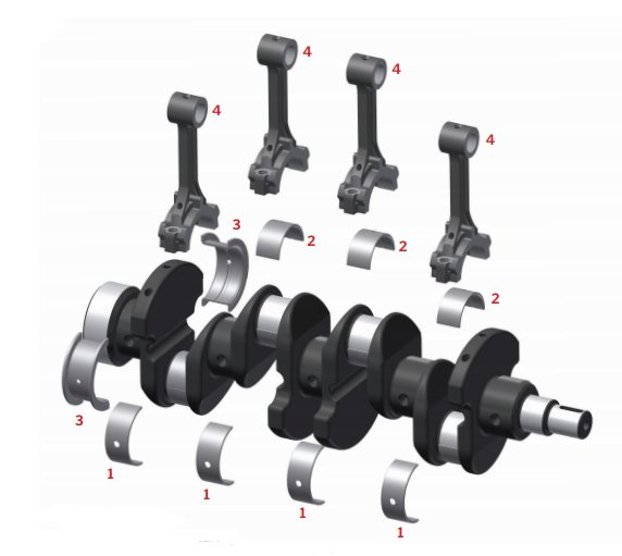
Crankshaft Engine Diagram
The crossplane or cross plane is a crankshaft design for v8 engines with a 900 angle between the cylinder banks.

Crankshaft engine diagram. The basic crankshaft shown above is from an inline 4 cylinder engine. This is a topic covered in more detail in the article about engine layout. Despite the effective design of the crankshaft which has existed for centuries most of an engines power losses occur in the crankshaft area be it through heat vibration noise and friction. But one point of note is that in v shaped and w engines two connecting rods may share a single rod journal.
The crossplane crankshaft is the configuration used in most v8 road cars3d model. A v8 engine is an eight cylinder piston engine in which the cylinders share a common crankshaft and are arranged in a v configuration. Instead of the long shaft thats used in a multi cylinder car engine there is a single hub all of the pistons connecting rods connect to this hub. The crankshaft rotates within the engine block through use of main bearings and the crankpins.
To convert the reciprocating motion into rotation the crankshaft has crank throws or crankpins additional bearing surfaces whose axis is offset from that of the crank to which the big ends of the connecting rods from each cylinder attach. The big difference is in the crankshaft. The crankshaft sometimes casually abbreviated to crank is the part of an engine which translates reciprocating linear piston motion into rotation. A crankshaft is a rotating shaft which in conjunction with the connecting rods converts reciprocating motion of the pistons into rotational motioncrankshafts are commonly used in internal combustion engines and consist of a series of cranks and crankpins to which the connecting rods are attached.