Ct Cabinet Wiring Diagram

Electric Service Installation Manual Alexander Publications
2
Https Www Eaton Com Content Dam Eaton Products Low Voltage Power Distribution Controls Systems Meter Mounting Equipment Meter Breakers And Group Metering Current Transformer Metering Wp307005en Ringless Metering Ct Metering Pdf
Wiring new shop with 3 phase service doityourselfcom.

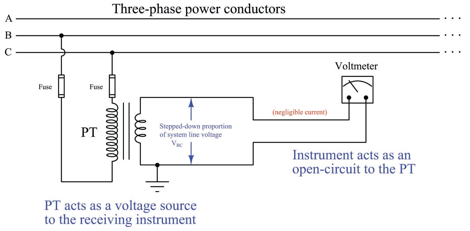
Ct cabinet wiring diagram. Switchgear main lt distribution panel making and wiring step by step. The polarity of each pair of terminals is indicated by a white and black dot on the label. Ct rated ct metering data subject to change without notice. Showing wiring from a current transformer in a cabinet to the test switch and to the meter.
At the ct cabinet bond the cabinet enclosure to your ground ring keeping the natural floating and call it a day. Single meter sockets without bypass meter mounting equipment 68 style suffixes 924 ms77 1 conduit hub 925 ss stainless steel 926 928 051hs fig. The problem i see is the bonding conductor that originates at the service disconnect natural bonds to the ground ring on its way to the ct cabinet enclosure is no longer just a gec. Ct cabinet parallel bonding electrician talk i want to split a 400 amp 3 ph service into two 200 amp ct cabinets metering equipment information and facility.
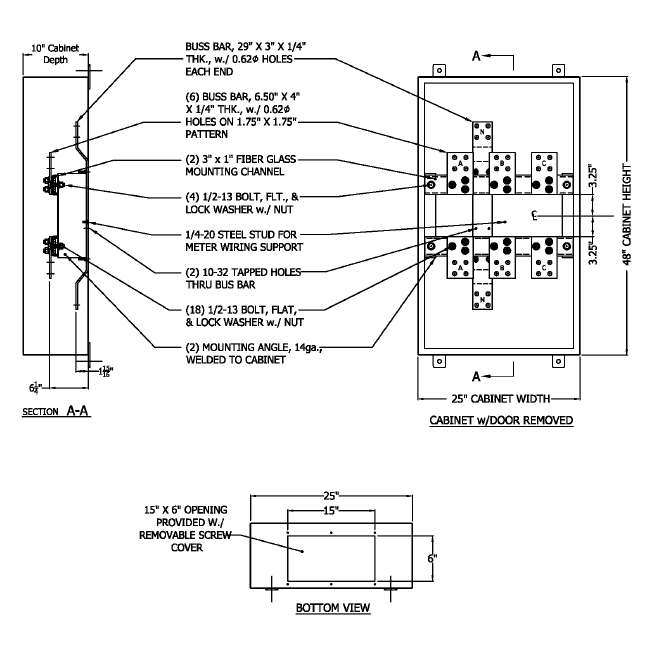
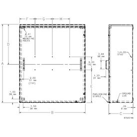
Ct current transformer wiring connections for commercial form 9s electric meter installation. Ct cabinet wiring diagram schema wiring diagram. How to wire 1600 amps ct cabinet bimcoach bim. All dimensions are in inches.
Architectural wiring diagrams produce a result the approximate locations and interconnections of receptacles lighting and unshakable electrical facilities in a building. Consult local utility for area acceptance. Be sure to connect the white wire to the phase terminal aligned with the white dot and the black wire to the terminal with the black dot. It is not necessary to run the bond from the ct cabinet back to the service disconnect if the ct cabinet is located on the supply side of the disconnect.
I can also do it without connection with one anther but the main reason behind this is that in real life we do our wiring like above diagram in our main power panel boards. In the above diagram i shown three ammeters current transformers in the above ct wiring diagram i common a wire of all ct s my means that i connect ct one connection with one another. 1 top provision 1a 4f. Interconnecting wire routes may be shown approximately.
2 the ct cables should be kept as short as possible use 25mm cable to maintain accuracy 3 cts match the ratio of the meter being fitted eg 2005 amp meter 200 amp cts 4 cts must be fitted onto the cable the correct way round so that k or p1 side is towards the mains and l or p2 is facing the load. Current transformer ct terminal teaching duration. F wiring trough 1600 a mp maximum company furnishes and installs.

Current Transformer An Overview Sciencedirect Topics
Https Www Nrc Gov Docs Ml1025 Ml102530301 Pdf
Pepco 400 To 800 Amp Nema 3r Ct Cabinet Phict83
Electrical Boxes Enclosures Cabinets And Racks Hoffman
Https Butlerrec Com Sites Bcrec Files Pdf Servicemeterdocuments Pdf
Https Www Rockymountainpower Net Content Dam Pcorp Documents En Pp Rmp Electric Service Requirements Esr Ch9 Pdf
Electrical Sensors Potential Transformers Pts And Current
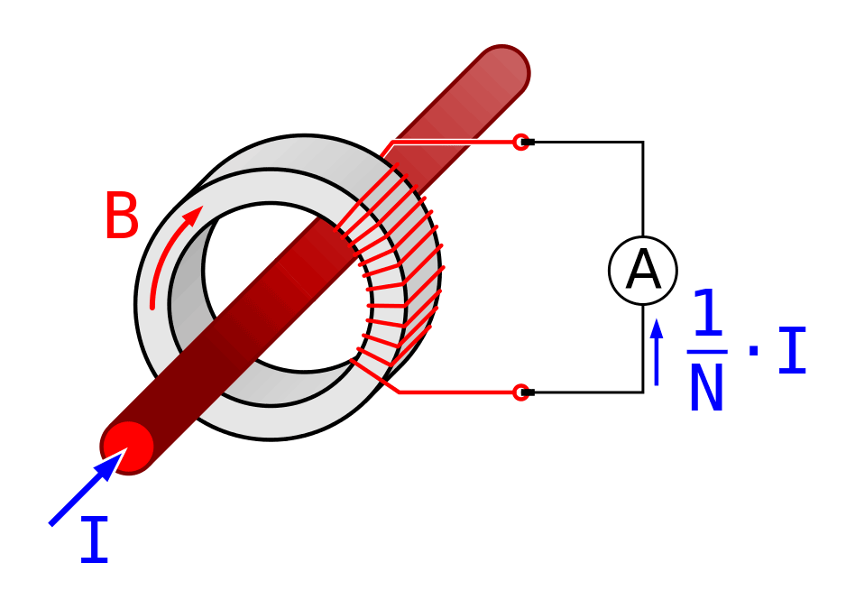
Current Transformer Basics Understanding Ratio Polarity And Class

Direct And Indirect Measurements Using Cts And Vts Eep
