Current Transformer Wiring Diagram
5cd60fc Ct Shorting Block Wiring Diagram Wiring Library
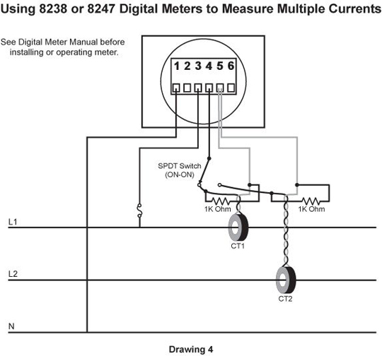
Switching Inputs To Digital Meters Part Ii Blue Sea Systems

Manual Changeover Switch Wiring Diagram For Portable Generator
We supply these meters on the assumption that they will be installed by a qualified electrician familiar with the installation of metering equipment ensure all current transformers are installed as per wiringdiagram which can also be.
Current transformer wiring diagram. Is a type of instrument transformer that is designed to produce an alternating current in its secondary winding which is proportional to the current being measured in its primarycurrent transformers reduce high voltage currents to a much lower value and provide a convenient way of safely monitoring the actual electrical current flowing in an ac. It reveals the elements of the circuit as streamlined shapes and the power as well as signal connections between the tools. Electrical wiring representations are composed of two points. How to wire current transformer with digital ampere meter ampere meter selector switch wiring with current transformers how to 3 phase current transformer wiring diagram with ampere meter note that if your ampere meter is 1005a then used only 1005a ratio current transformer.
This is about the diameter of a 8 awg thwn or thhn insulated conductor. Current transformer wiring diagram instructions note. The knee point voltage is less applicable for metering current transformers as their accuracy is generally much tighter but constrained within a very small bandwidth of the current transformer rating typically 12 to 15 times rated currenthowever the concept of knee point voltage is very pertinent to protection current transformers since they are necessarily exposed to currents of 20 or. A wiring diagram is a kind of schematic which utilizes abstract pictorial icons to show all the affiliations of parts in a system.
Current transformer wiring diagram whats wiring diagram. Collection of 3 phase current transformer wiring diagram. In the above diagram i shown three ammeters current transformers. Refer to the current transformer wire extension page for more information.
A wiring diagram is a simplified standard photographic representation of an electrical circuit. A complete guide of current transformer installation and wiring connection with ammeters. The current transformer ct. 3 phase current transformer wiring diagram sample transformer wiring diagrams three phase 4k wallpapers design.
Electricalonline4u a platform to learn electrical wiring single phase 3 phase wiring controlling hvac. In the below 3 phase current transformer wiring diagram with amp. Icons that stand for the parts in the circuit as well as lines that stand for the links in between them. The diameter of ct twisted pair lead wires is about 0213 in.
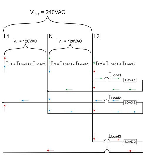
Current Flow In 120 240 Volt Ac Systems Blue Sea Systems

Wiring Diagram Of Three Phase Four Wire System Ammeter Page 1
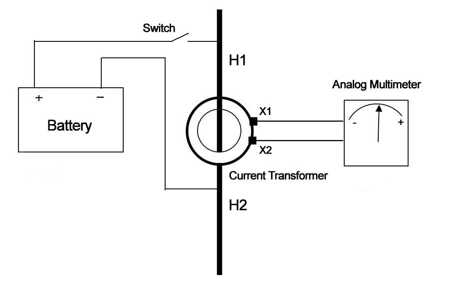
Current Transformer Basics Understanding Ratio Polarity And Class
Summation Ct Wiring Diagram

Abb Current Transformer Wiring Diagram

Current Transformer Wikipedia
Kw1m Eco Power Meter Dimensions Automation Controls Industrial

3 Phase Current Transformer Wiring Diagram Roti Fuse8 Klictravel Nl

Current Transformer Basics And The Current Transformer
