Dc Servo Motor Circuit Diagram
Dc Servo Motor Driver Electronics Lab
Brushed Dc Servo Motor Driver 1 Electronics Lab

Dc Servo Motors Theory Of Dc Servo Motor Electrical4u
The torque that is generated at the output shaft can be scaled up or scaled down by using a gear train.
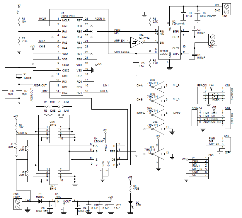
Dc servo motor circuit diagram. A wiring diagram is a simplified conventional pictorial depiction of an electric circuit. It shows the components of the circuit as streamlined forms and the power and signal connections in between the devices. Variety of servo motor wiring diagram. Separately excited dc servo motor dc servo motor theory.
Dc servo motor driver electronic circuit diagram circuit and wiring diagram download for automotive car motorcycle truck audio radio electronic devices home and house appliances published on 13 jun 2016. A servo is a small device that has an output shaft. A dc servo motor is an assembly of four major components namely a dc motor a position sensing device a gear assembly and a control circuit. Here sub micro size servo motor is taken as a target device and we developed servo motor driver circuit for that motor.
Servo motors are widely used in different types of applications and suitable for movement or rotation based mechatronic needs. Field controlled dc servo motor circuit diagram. As from the above characteristics it is seen that the slope is negative. It uses the cmos ic 7555 in the astable mode to generate pulses to drive the servo motor.
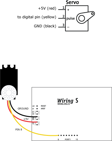
The transfer function of armature controlled dc servo motor is shown below. Thus a negative slope provides viscous damping for the servo drive system. Field control has some specific advantages over armature control and on the other hand armature control has also some specific. Every servo motors will have three terminals one for.
Dc motors can be made to turn either clockwise or counter clockwise by changing the polarity of the voltage applied to their terminals. Servo motors are basically rotary actuators that enable precise control of angular position acceleration and velocity in various embedded system applications. The below figure shows the parts that consisting in rc servo motors in which small dc motor is employed for driving the loads at precise speed and position. Most of the high power servo motors are mainly dc.
This is the simple basic design of servo motor controller with pulse generator. Commonly having a rotation limit of 90 o to 180 o servo motors are dc motors equipped with servo mechanism to sense and control angular positionthey are used where there is a need for accurate shaft movement or position. Osv a s k 1 js 2 bsl a s r a 1 k 1 k b k sjs 2 bsl a sr a. In this method of speed control a variable input voltage is applied to the field winding of dc motor while keeping the armature current constant.
The torque speed characteristics of the motor is shown below.
Servomotor Learning Wiring

Block Diagram Of Separately Excited Dc Servo Motor Download

How Servo Motors Work Servo Motor Controllers
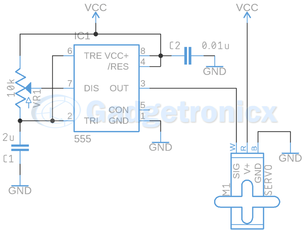
Servo Motor Driver Circuit Using Ic 555 Gadgetronicx

Electronics 101 Servo Motor Celebratelife24x7

Diy Servo Motor Cheap And With Plenty Muscle Bayesian Adventures

Considerations For The Control Of Dc Micromotors

Dc Servo Motors Theory Of Dc Servo Motor Electrical4u
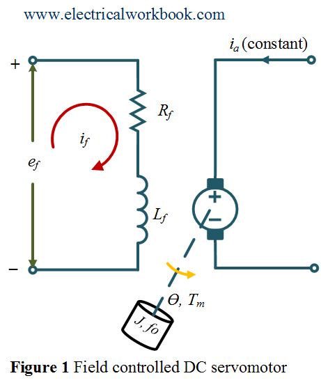
Field Controlled Dc Servomotor Electricalworkbook
