Diagram Of Welding Transformer
How To Modify The Cp 250ts For Single Phase And Short Arc Welding

Welding Transformer Working Principle And Applications Technical
Http Www Ijitee Org Wp Content Uploads Papers V9i3 F3631048619 Pdf
Homemade spot welder diy.

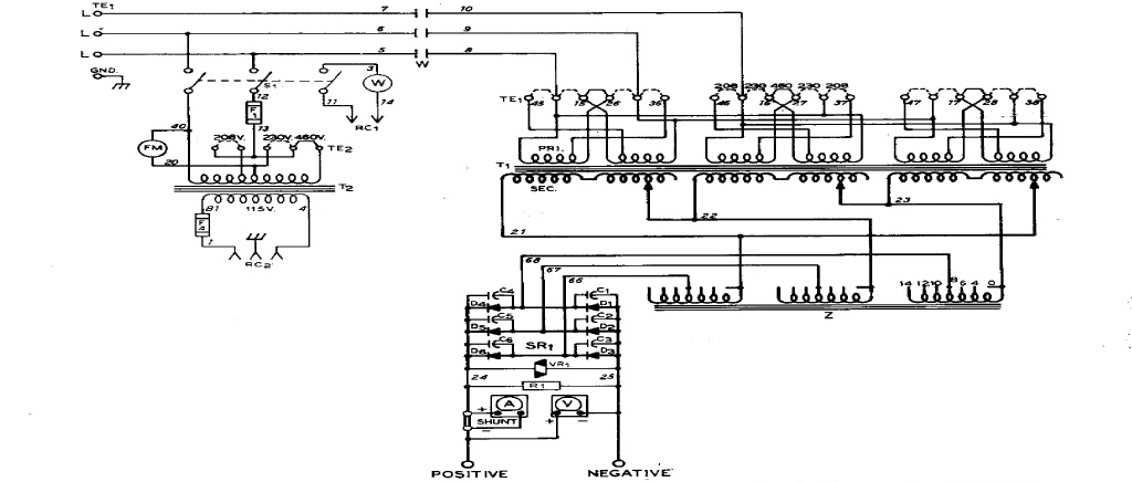
Diagram of welding transformer. Smps welding inverter circuit. Operating principles of a welding transformer. The amount of current can be adjusted by inserting a reactance coil into the circuit. 111 explaining the transformer 200 drawing of wiring up the transformers 412 wiring up the transformers explained with batteries 700 wiring up the transf.
After reading this article you will learn about 1. The welding circuits are properly earthed to protect the welder in the event of a breakdown in the transformer and causing main supply voltage to come into contact with welding side circuit of the transformer. The impedance of welding transformer may be higher than that of the impedance of a general purpose transformer. The welding current at the full wave rectifier output is normally controlled.
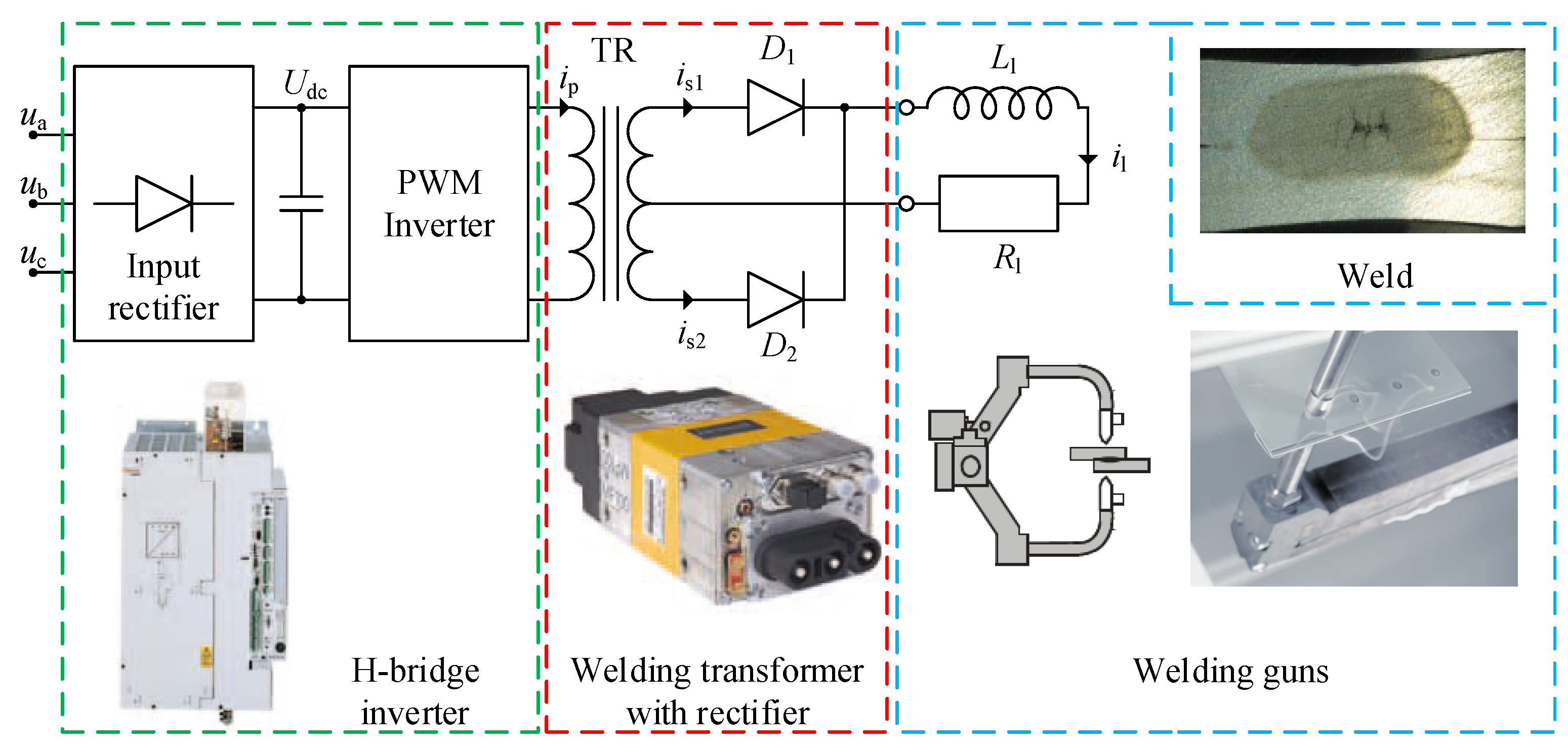
Operating principles of a welding transformer 2. Three states of matter. If you are looking for an option to replace conventional welding transformer the welding inverter is the best choice. Michael paley 1008620 views.
Ordinary transformer wired as an autotransformer to buck the line voltage down. Simplified diagram of the weld force system. Welding inverter is handy and runs on dc current. How to make spot welder machine with power control.
The impedance of welding transformer may play a role in the process of establishing an arc and controlling the current. Principle requirement and types article shared by. Elihu thomson his original jews harp welding transformer1 figure 2. Simplified diagram of a welding transformer4 figure 5.
The prime advantage of an autotransformer is that the same boosting or bucking function is obtained with only a single winding making it cheaper and lighter to manufacture than a regular isolating transformer having both primary and secondary windings. The welding side provides current setting range. Large welding transformers are most likely to be designed for three phase input. Resistance welding controls and applications original 1989 a revised 1997 b revised.
So the usage of welding transformer has significant role in welding compared to a motor generator set. In an ac welding arc the current remains nearly sinusoidal while the voltage is. Last updated on july 3 2019 by swagatam 65 comments.
How Is A Welding Transformer Constructed Quora

Eer43x15 Welder Welding Transformer Used For Welding Machine View
Welding Transformer Design Calculation
Transformer Basics Working Principle Construction Types Applications
Http Sininenankka Dy Fi Sami Welding 20transformer 20principle 20requirement 20and 20types Pdf

Welding Circuit Diagram Wiring Advance Electrical Schematic Arc
Energies Free Full Text Impact Of The Winding Arrangement On

Welding Transformer Circuit Diagram Wiring Diagram

Adjustable Transformer For Welding
