Diesel Engine Pv Diagram
Https Encrypted Tbn0 Gstatic Com Images Q Tbn 3aand9gcsddn4y0nyvkt Jojhheieo5repvymyujdlwp0swamsquaqlzcyrfcydrmpthgon2i Usqp Cau

Thermodynamics
4 5 Air Standard Diesel Cycle Nptel Indian Institute Of
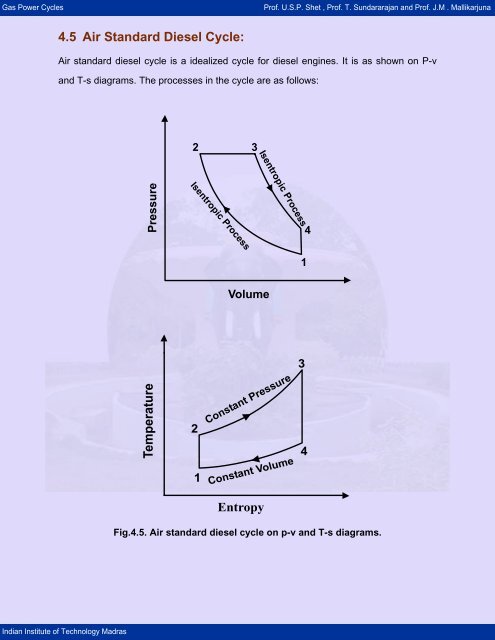
Diesel is used as fuel in this cycle as it can be compressed at higher compression ratio.
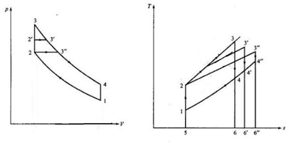
Diesel engine pv diagram. Diesel cycle can be understood well if you refer its p v and t s diagrams. In this article it is shown an ideal diesel cycle in which there are a lot of assumptions differs from actual diesel cyclethe main differences between the actual and ideal diesel engine appear in the figure. Diesel cycle is similar to otto cycle except in the fact that it has one constant pressure process instead of a constant volume process in otto cycle. Here is a picture gallery about pv diagram for diesel engine complete with the description of the image please find the image you need.
It is widely used in diesel engines. Diesel cycle is a gas power cycle invented by rudolph diesel in the year 1897. Talkdiesel cycle wikipedia regarding pv diagram for diesel engine image size 420 x 420 px and to view image details please click the image. All heat engines are characterized by a pressure volume diagram also known as pv diagram which basically shows the variation of the pressure in the cylinder function of its volume for a complete engine cycle.
For an actual cycle the shape of the pv diagram is similar to the ideal but the area work enclosed by the pv diagram is always less than the ideal value. Following are 4 stages of an ideal diesel cycle. Diesel engines are used in aircraft automobiles power. In reality the ideal cycle does not occur and there are many losses associated with each process.
At this point let p1 and t1 and v1 be the pressure temperature and volume of the air. Hi guys this video is an animation explaining the working of diesel cycle. The diesel cycle was invented by rudolph diesel in 1893. The pressure volume diagram of both theoretical and practical concepts are explained.
I hereby explain the differences between theoretical and actual pv diagram for a ci engine in tamil. The diesel cycle is a combustion process of a reciprocating internal combustion enginein it fuel is ignited by heat generated during the compression of air in the combustion chamber into which fuel is then injected. The main differences between the actual and ideal diesel engine appear in the figure. He put forward an idea by which we can attain higher thermal efficiency with a high compression ratio.
This is in contrast to igniting the fuel air mixture with a spark plug as in the otto cycle four strokepetrol engine. All diesel engine works on this cycle. Comparison of actual and ideal diesel cycles.

Diesel Cycle Pv And Ts Diagram Diesel Cycle Efficiency

Actual And Ideal Diesel Cycle

Asymmetric Twin Scroll Turbocharging In Diesel Engines For Energy

Notes On Diesel Engine And Entropy And Disorder Grade 11

Bloggers April 2016

The Diesel Engine
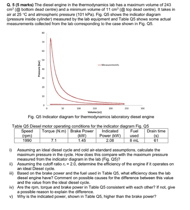
Solved Q 5 5 Marks The Diesel Engine In The Thermodyna
Comparison Of Theoretical Cycles Of Marine Diesel Engines Dual

4 Stroke Diesel Engine
