Digital Signal Processing Block Diagram Explanation
In source coding the encoder converts the digital signal generated at the source output into another signal in digital form.

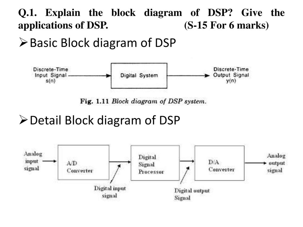
Digital signal processing block diagram explanation. With no invariant sections no front cover texts and no back cover textsa copy of the license is included in the section entitled gnu free documentation license. Block diagrams are widely used by engineers for controls signal processing communications and mechatronics. Selesnick el 713 lecture notes 1. In this diagram three basic signal processing operations have been included.
Different source coding techniques are pcm pulse code modulation dmdelta modulation. Sample the sample block function is to sample the input analog signal at a specific time interval. A block diagram consists of blocks that represent different parts of a system and signal lines that define the relationship between the blocks. The digital signals processed in this manner are a sequence of numbers that represent samples of a continuous variable in a domain such as time space or frequency.
Types of signals a signal is a function that contains information which can be trans mitted displayed or manipulated. The conversion from analog signal to a digital signal in an analog to digital converter is explained below using the block diagram given above. Engineers build and use block diagrams to. Digital signal processing dsp is the use of digital processing such as by computers or more specialized digital signal processors to perform a wide variety of signal processing operations.
Digital signal processing introduction 1types of signals 2digital vs analog signal processing 3applications 4basic block diagram 5dsp history i.