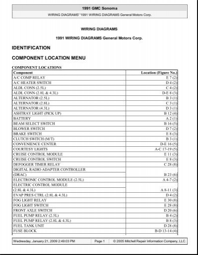
Drac Wiring Diagram

1piece Heater Band Wiring Diagrams Proheat Inc 502 2221402 Band

Vdo Instruments Wiring Diagram Diagram Base Website Wiring Diagram

Diagram Based Wiring Diagram Kawasaki Ninja Rr Completed
I would look at the wiring around the bellhousing first to be sure you have not pinched any wires.
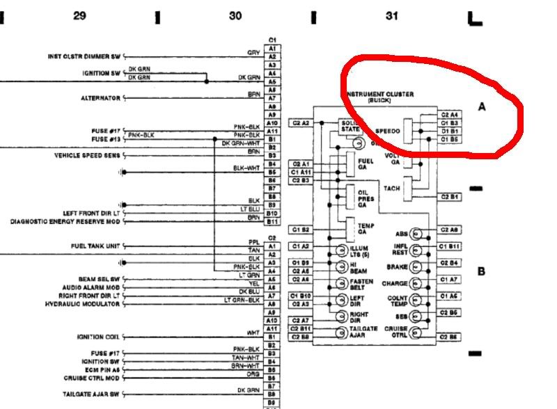
Drac wiring diagram. The drac controls the speedometer not the pcm. Drac vssb gm speedometer module replacement and calibration 1989 2002 mixed applications 62l diesel 65l diesel tbi gas. When swapping an ls engine into a 1988 1998 chevy truck the donor vehicle wiring harness must be modified to work with the swapped vehicle or a new harness must be made. One says yellow wire from vss to speedo but then i read that there is a buffer box the vss goes through from to they had a separate drac module outside of the cluster c12 vehicle speed sensor input.
On that truck behind the glove box is the pcm and another white colored box called a drac. I had the people at howell performance make my wiring harness. This video shows where i. Ground at terminal c8 3.
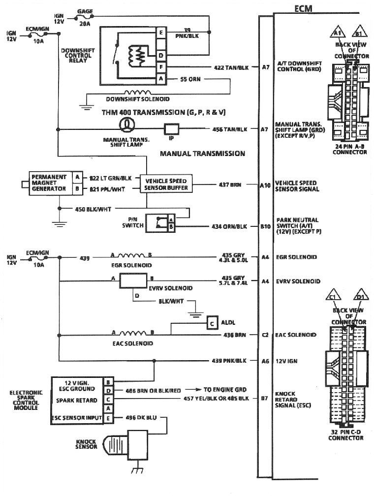
With an overview of what the drac does lets take a look at the signals the drac needs to oper ate. Figure 3 shows a basic drac wiring diagram. Look into replacing it. Now it is a 1993 with a 53 liter 4l60 lm4 out of an envoy.
Found one diagram for a drac and went to the truck to check it out. Yes 7747 applications expect 2k ppm. Jump to latest follow. If it did use a buffer you can probably wire the drac of the.
Not the way i like to work however. Vss and vehicle speed signal buffer wiring diagram removal installation see figure 2 disconnect the negative battery chevy tbi all 89 parts to include wiring harness and steering column. The ecm should get its speed from the drac since its responsible for converting the pulses from the vss to pulse per mile readings the various modules want. I can cross check a 7427 wiring diagram against the drac outputs to determine speed signal frequency on f13.
They were developed when the speedometer cable drove the speed sensor. Jump to latest follow. Started the truck and the speedometer works. I couldnt help myself with the battery hooked up and everything i just jammed the plug home.
Also check your trans and gauge fuses. A clean ac voltage signal of sufficient amplitude from the speed sensor between termi nals c7 and c12. Where do i connect this lead to make the. Switched battery hot with ignition switch on at terminal c9 2.
The 9 pin connector i have seemed to fit. Digital ratio adapter calibrator vehicle speed sensor buffer tbi vssb module tbi drac module. The output speed not from drac selection might be shown in the manual trans comparison thread currently running.
Using An Electronic Speedo With Tbi And 700r4 The 1947
Https Www Studocu Com Es Ar Document Universidad Tecnologica Nacional Mantenimiento Informes Modulo Drac Para Vehiculos Gm 7123602 View
Using An Electronic Speedo With Tbi And 700r4 The 1947

Wrg 9159 Geovision Cameras Netgear Switch Wiring Diagram
Wiring Diagrams Justanswer

5915a Wrg 7679 Pioneer Car Audio Wiring Deh Pd7 Wiring Library

D R A C Module Gm Square Body 1973 1987 Gm Truck Forum

What Wire Goes Where Third Generation F Body Message Boards

A Polar Transmitter Based On A Dco And Dpa Circuits From 2 For
