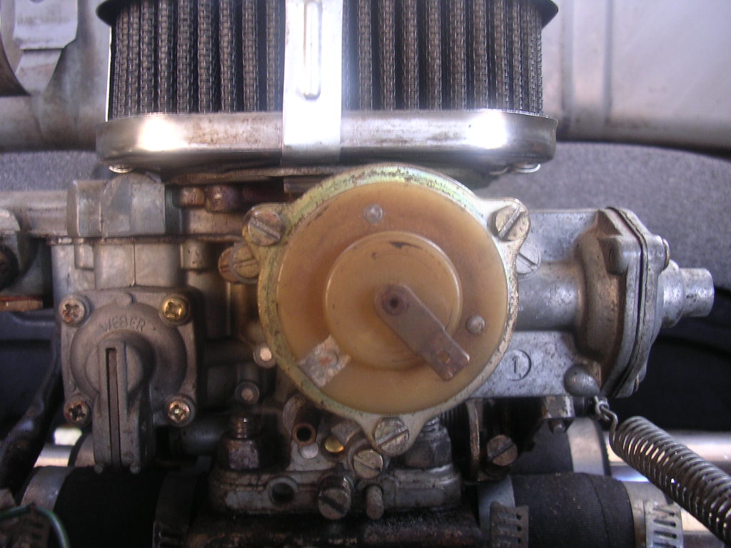
Electric Choke Wiring Diagram
The electric power source allows for quicker choke opening for emmission purposes.

Electric choke wiring diagram. Wiring diagram of single tube light installation with electronic ballast. When using any of the other american autowire wiring kits such as a classic update power plus highway or builder series you simply need to take any ignition fused 12 volt feed use about a 10 amp fused and connect it to your electric choke assembly. Hooking up the electric choke on an edelbrock afb carb. Automatic choke operation dellorto carburettor how does it works and whats inside duration.
This would not be enough voltage to properly operate your electric choke. For demonstration on adjustment of the edelbrock carburetor i recommend this link http. One end of a starter is connected to pin 2 of terminal 1 and another end of the starter is connected to the pin 2 of terminal 2. Especially with stock wiring.
Chavy levy 148297 views. Wiring diagram electric choke you are welcome to our site this is images about wiring diagram electric choke posted by alice ferreira in diagram category on nov 13 you can also find other images like wiring diagram parts diagram replacement parts electrical diagram repair manuals engine diagram engine scheme wiring harness. The splices done to the hazard relay wiring were actually done on the harness i had to use to hook up the solid state relay meaning the mustangs original wiring wasnt touched much the radio has a constant source of power to maintain the clock station presets and settings. Installation instructions for electric choke kit pns 45 224 45 224s 745 224 introduction.
Electric chokes are somewhat subject to heating up and shorting out. These kits can be used to convert holley carburetors that were originally equipped with a hot air or manually operated choke to full automaticelectric operation. The radio and electric choke are protected by a fuse. Congratulations on your purchase of a new electric choke kit from holley.
One terminal of choke or ballast is connected to port 1 and another terminal is connected to pin 1 of terminal 1. One thing that everyone has missed here is that it must be a fused circuit. Tapping off of the hot or high tension side of the ballast resistor is fine however you must install an inline fuse as the ignition is completely unfused. Any heavy draw electrical retrofit fuel pump headlamp ignition system etc to an early chassis should have its own fusedproper wire size relayed power source.