Electric Circuit Diagram With Ammeter And Voltmeter

Lessons In Electric Circuits Volume I Dc Chapter 8
Voltmeters And Ammeters Boundless Physics

Phys345 Laboratory Introduction To Electrical Measurements
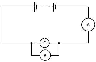
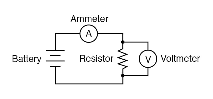
In order for an ammeter to measure a devices current it must be connected in series to that device.
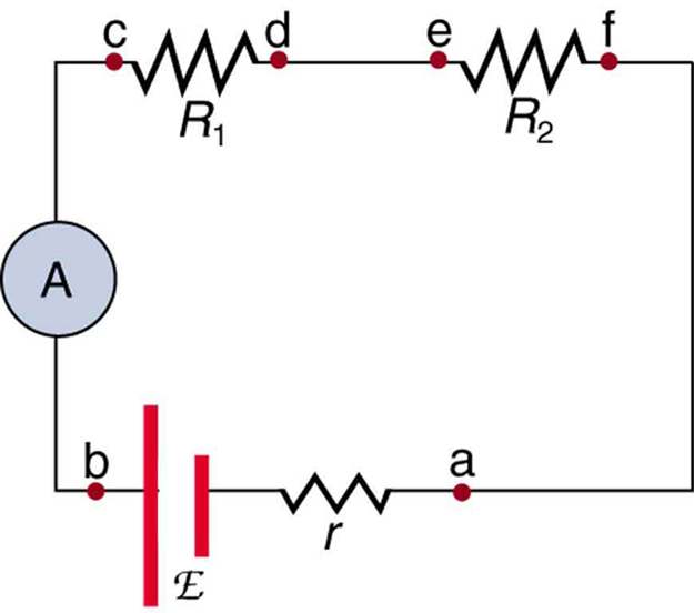
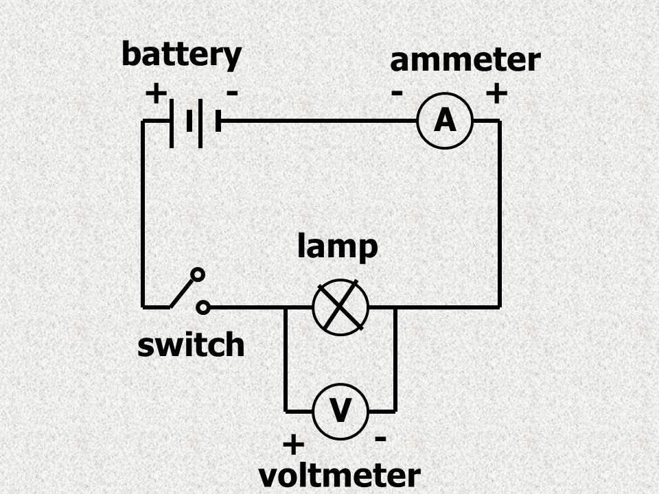
Electric circuit diagram with ammeter and voltmeter. Here we will discuss both with ammeter and voltmeter circuit diagram. In the diagram at right an ammeter is connected correctly to measure the current flowing through the circuit. Electric current and direction of electric current part 03 duration. Extra question 12 draw a circuit diagram of an electric circuit containing a cell a key an ammeter a resistor of 2 w in series with a combination of two resistors 4 w each in parallel and a voltmeter across the parallel combination.
First you have to know there basics of an ammeter and voltmeter. Voltmeter circuit theory. It is a perfect addition to any diy laboratory power supply battery chargers. Circuit diagram ammeter voltmeter duration.
Drawing electric circuits with volt meters and ammeters. Voltmeter ammeter description this voltmeter ammeter was designed to measure output voltage of 0 70v 0 500v with 100mv resolution and 0 10a or more current with 10ma resolution. In the electric circuit diagram at right possible locations of an ammeter and a voltmeter are indicated by circles 1 2 3 and 4. Science and maths.
An ammeter is always connected in series in a circuit because when an ammeter is connected in series it does not appreciably change the. An ammeter is used to measure the current passing through it which means the current which we want to measu. This is necessary because objects in series experience the same current. The answer is very simple.
An ammeter is a low resistance galvanometer used to measure strength of current in an electrical circuit.
How Will You Connect Voltmeter And Ammeter In Electric Circuit لم
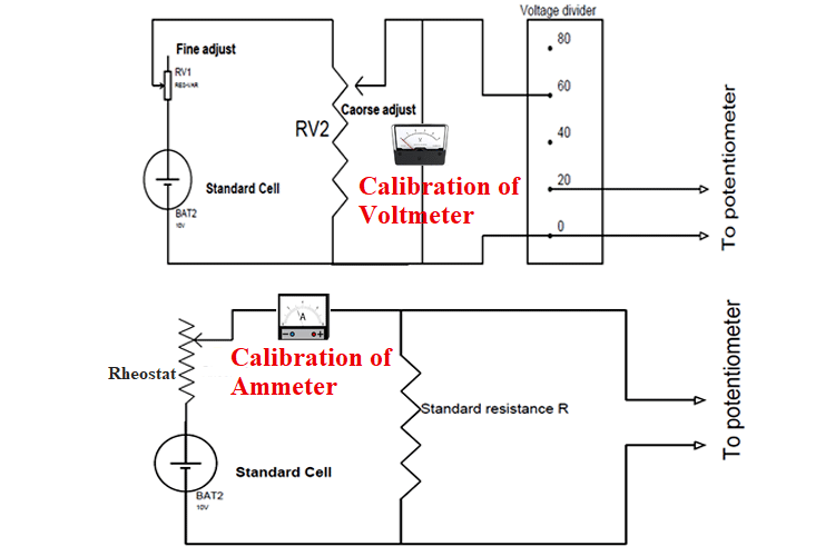
Calibration Of Ammeter Voltmeter And Wattmeter Using Potentiometer
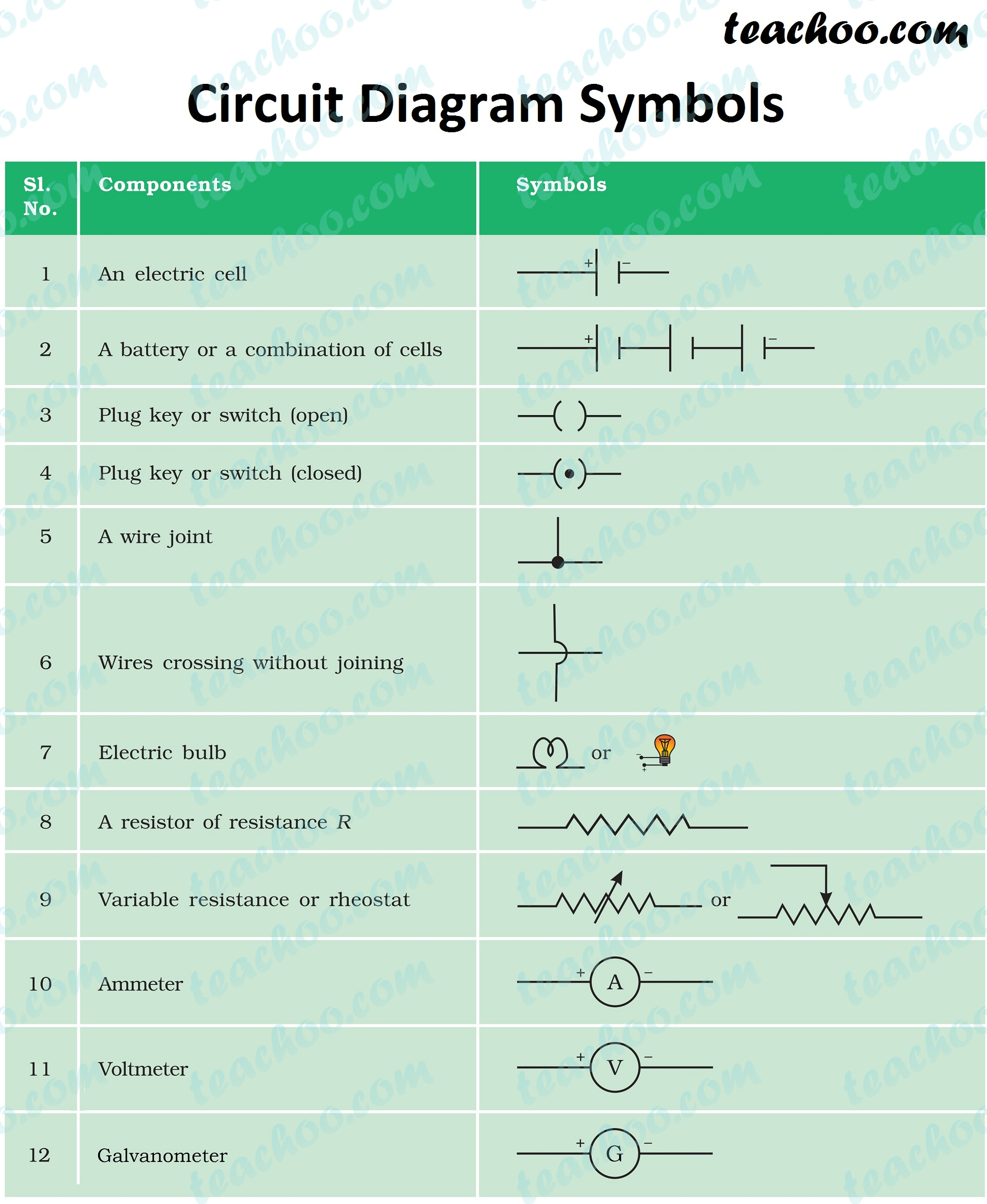
Electric Circuit Diagram Symbol Open And Closed Circuit Teachoo
Circuit Diagrams Basic Electricity Ppt Video Online Download

How To Make A Digital Voltmeter Ammeter Module Circuits

Series Circuits Series And Parallel Circuits Siyavula

Ne 3991 Circuit Diagram Ammeter On Note The Meter S Indication Of
Ohm S Law Basic Concepts And Test Equipment Electronics Textbook
9 5 Ohm S Law Physics Libretexts
