Electrical Circuit Diagram Components

Electrical And Electronic Schematic Diagrams Part 1

Electrical Symbols Resistors Simple Switched Supply Circuit

Electronic Symbol Wikipedia
It really helps in showing the interconnections in different equipment such as electrical panel and distribution boxes etc.

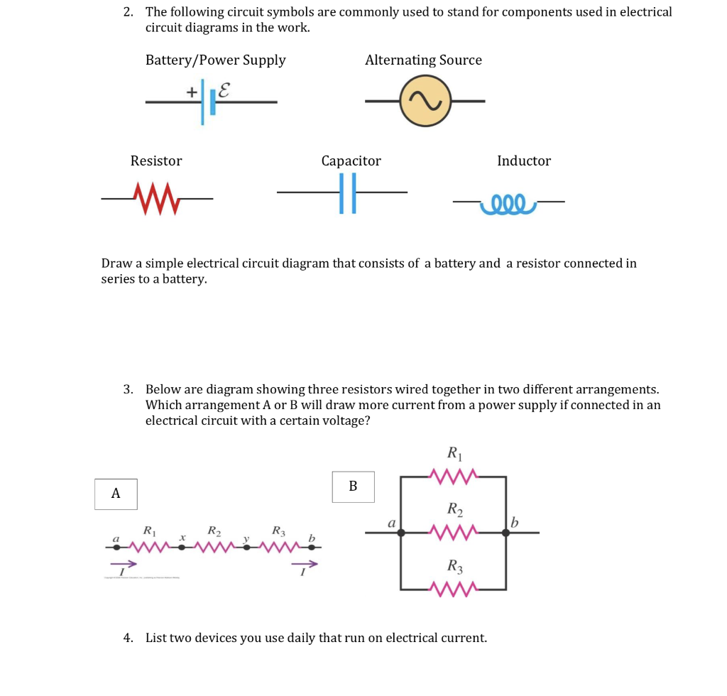
Electrical circuit diagram components. The presentation of the interconnections between circuit components in. An electrical circuit consists of batteries resistors inductors capacitors switches or transistors. Circuit diagram is a free application for making electronic circuit diagrams and exporting them as images. Symbols even more the electronic components have terminals and each will have its own name and polarities.
Wiring diagram shows a pictorial view of the components such that it resembles its electrical connection arrangement and position in real circuit. As long as the copper wire is allowed to itself the electrons drift between the. The symbols represent electrical and electronic components. A circuit is a closed path where electrons flow in a wire.
A resistor restricts or limits the flow of electrical current. They are mostly used for wiring installation in home and industries. Based on the type of connection of active and passive components with the source a circuit can be classified into series and parallel circuits. A circuit diagram is a simplified representation of the components of an electrical circuit using either the images of the distinct parts or standard symbols.
An electrical network consists of a closed loop. An electronic component is any basic discrete device or physical entity in an electronic system used to affect electrons or their associated fieldselectronic components are mostly industrial products available in a singular form and are not to be confused with electrical elements which are conceptual abstractions representing idealized electronic components. Share on tumblr the symbols are very important to represent electronic components in a circuit diagram without electronic symbol the design of circuit and schematics are very difficult and also knowing the components is very must to read the circuit diagram representation. Electrical symbols and electronic circuit symbols are used for drawing schematic diagram.
The following symbols show the different components that can be found in an electrical circuit. It shows the relative positions of all the elements and their connections to one another. A circuit diagram electrical diagram elementary diagram electronic schematic is a graphical representation of an electrical circuita pictorial circuit diagram uses simple images of components while a schematic diagram shows the components and interconnections of the circuit using standardized symbolic representations. Electrical circuit is an interconnection of electrical components.
A fixed resistor has a resistance.
Https Encrypted Tbn0 Gstatic Com Images Q Tbn 3aand9gcquqno7bkut9elog9rxs3fbexi32wijkni Biebfaqpolegiizt Usqp Cau

Electronics Club Circuit Symbols
Solved The Following Circuit Symbols Are Commonly Used To
.PNG)
Electrical Circuits Presentation Physics
Electric Circuit Symbols Ausgrid

What Is The Difference Between Schematic Diagram And Wiring

Skill Builder Reading Circuit Diagrams Make

How To Read Car Wiring Diagrams For Beginners Emanualonline Blog
Flat Schematics Vs Hierarchical Design
