Electrical Relay Diagram

Electrical Relay And Solid State Relays For Switching
Relay Logic Wikipedia
Starter Interrupt Relay Diagrams
Variety of electric fuel pump relay wiring diagram.

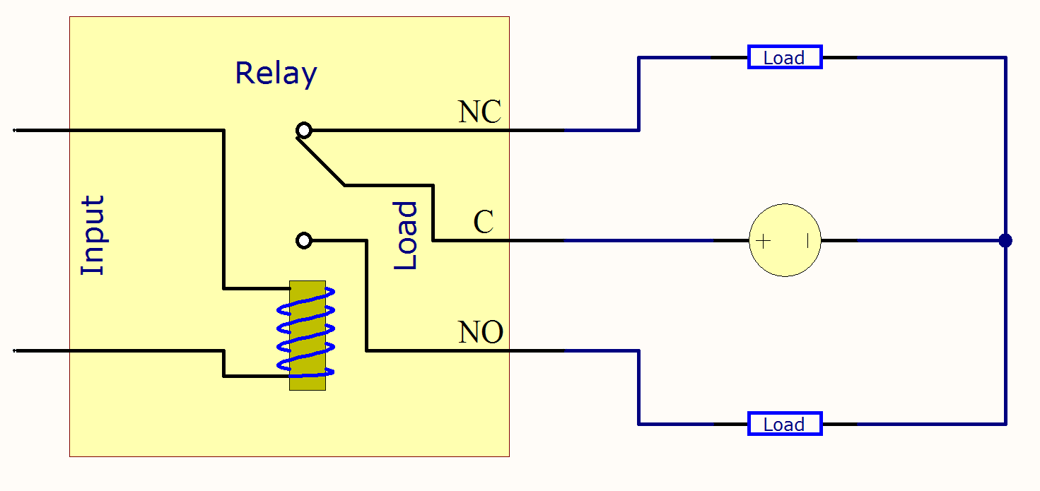
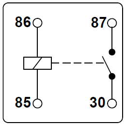
Electrical relay diagram. This diagram represents the basic circuit of solid state relays. A relays electrical life is the number of operations openings and closings the contacts can perform with electrical current at a given current rating. The following table lists some. Relay symbols and electromagnets.
Most of the time a small voltage or current is used to switch other voltages or higher currents that may be electromechanical or fully electronic type. Electrical symbols switches and relays. A wiring diagram is a simplified standard photographic depiction of an electrical circuit. Normally open normally closed thermal over load grd ch recp pl tr tr tr tr cr m.
This pinout image is only a 2 pole diagram for room on the page purposes but you can get the picture here with this one since a 3 pole will just have 1 more set of contacts. Electrical symbols are used to represent various electrical and electronic devices in a schematic diagram of an electrical or electronic circuit. We begin with a basics fuel pump relay diagram. Contacts time delay after coil normally open normally closed normally open normally closed relay etc.
It shows the elements of the circuit as streamlined shapes and the power as well as signal links in between the gadgets. Most of the electrical symbols can be changed in their appearance styles and colors according to users requirements. A relays contact electrical life ratings range from 100000 to 500000 cycles. Cont ground chassis or frame not necessarily grounded plug and recp.
If you need a relay diagram that is not included in the 76 relay wiring diagrams shown below please search our forums or post a request for a new relay diagram in our relay forum. The square relay pinout shows how the relay socket is configured for wiring. A relay is an electrically operated switchit consists of a set of input terminals for a single or multiple control signals and a set of operating contact terminals. Dozens of the most popular 12v relay wiring diagrams created for our site and members all in one place.
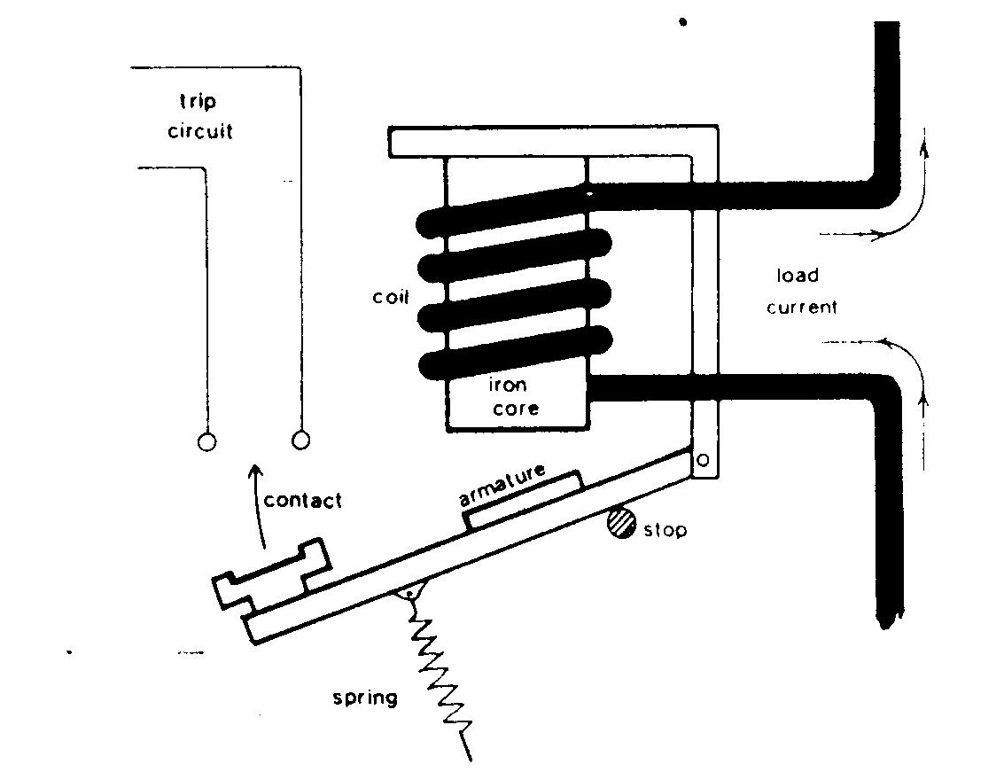
The relay are switching devices activated by signals. This feature is not available right now. A wiring diagram is a simplified traditional pictorial depiction of an electrical circuit. It reveals the components of the circuit as simplified shapes and also the power and signal connections in between the tools.
Relays are used where it is necessary to control a circuit by an independent low power signal.

Dpdt 110vac 10a 8 Pin Octal Power Relay Technical Data
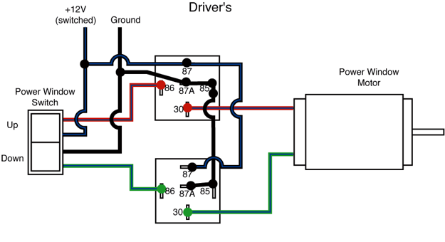
Power Window Relays 4 Post Vs 5 Post Rx7club Com Mazda Rx7 Forum

Staircase Timer Wiring Diagram Using On Delay Timer And Relay Timer
Solid State Relay Or Solid State Switch
Mechanical Relay Primer Phidgets Support
Automotive Relay Guide 12 Volt Planet
Maintenance Of Electrical Relay On Ships Electrical Circuit

Electromechanical Relay Logic Worksheet Digital Circuits

5 Pin Relay Wiring Diagram 24 Volt Diagram Base Website 24 Volt Venndiagramgenerator Teatromandanicibarcellona It
