Electrical Schematic Symbol For Solenoid Valve

What Is A 3 Way Solenoid Valve Instrumentation Tools
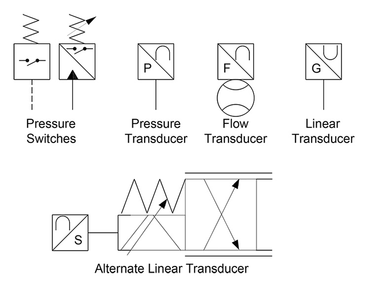
Hydraulic Symbology 301 Electrical And Electronic Symbols
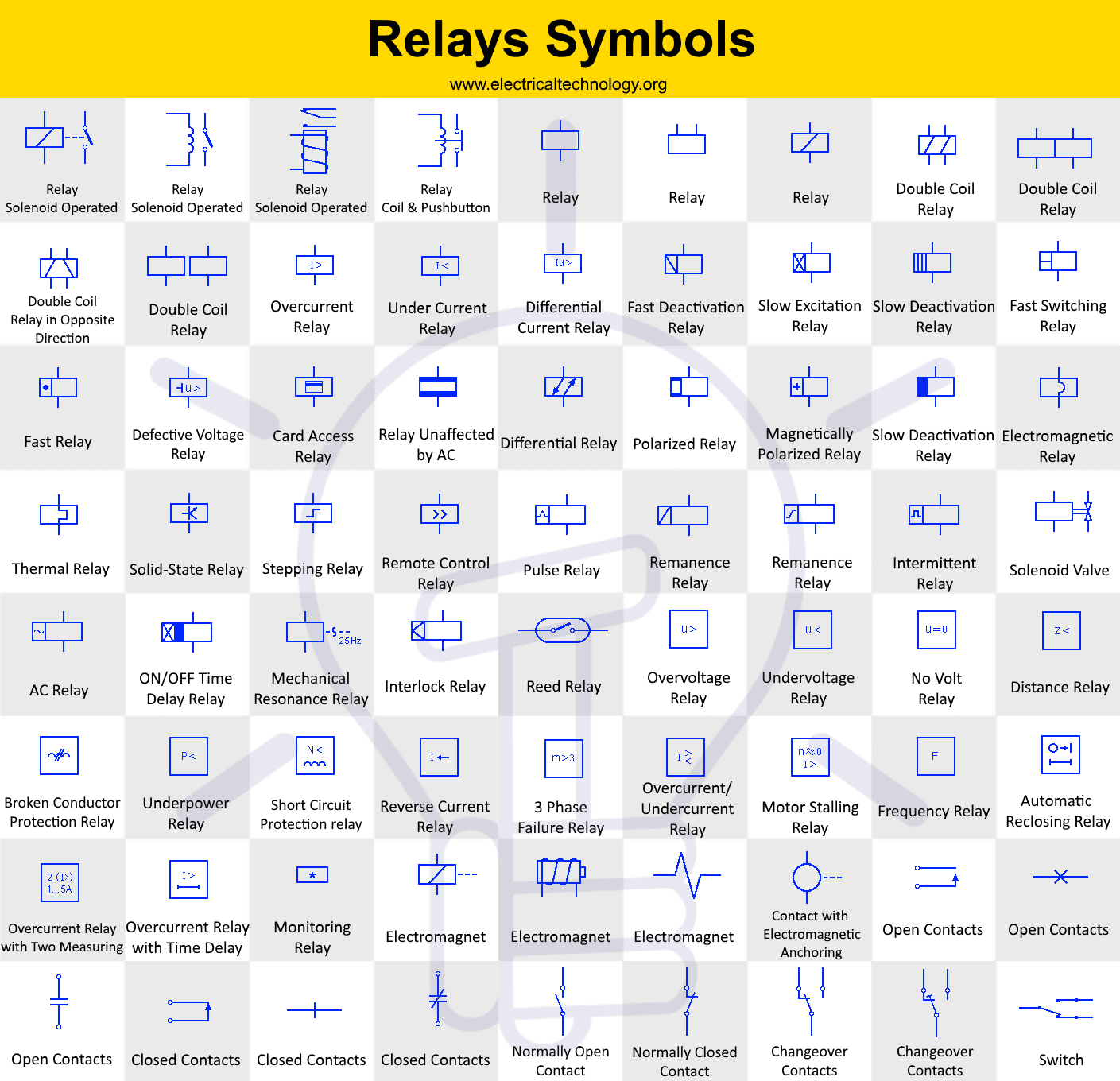
Relays Symbols Coil Solenoid Electromagnet Contacts Symbols
0800 808 7799 int.

Electrical schematic symbol for solenoid valve. Horizontal symbol vertical symbol description hsv1 vsv1 standard solenoid valve hsvc1 vsvc1 standard solenoid valve with connection hsv1y1 vsv1y1 open solenoid valve closing hsv1y1a vsv1y1a open solenoid valve closing according to solenoid hsv1y3 vsv1y3 magnetic brake hsv1y4 vsv1y4 electromagnetic brake hsv21 vsv21 solenoid valve auxiliary normally open contact hsv22 vsv22 solenoid valve. This example shows a normally open 22 way solenoid valve symbol. Understanding ansi iso schematic symbols for fluid power and pneumatic components are used to identify and graphically denote the function and operation of piped control systems. A wiring diagram is a streamlined traditional pictorial representation of an electric circuit.
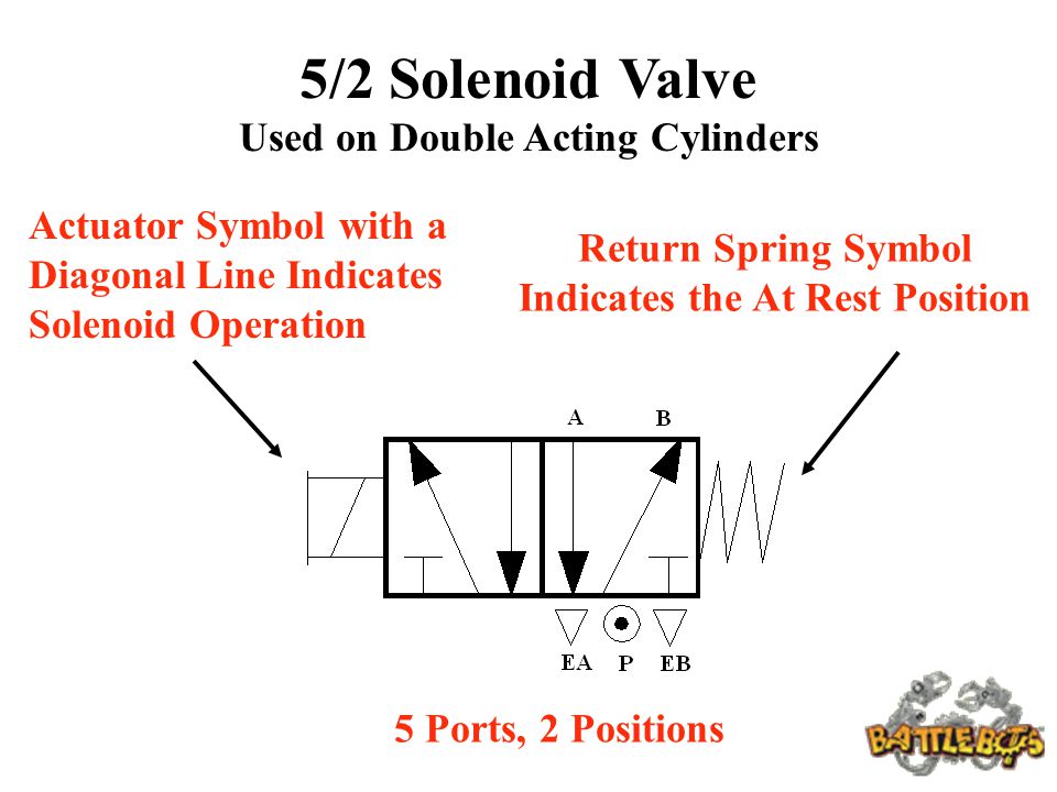
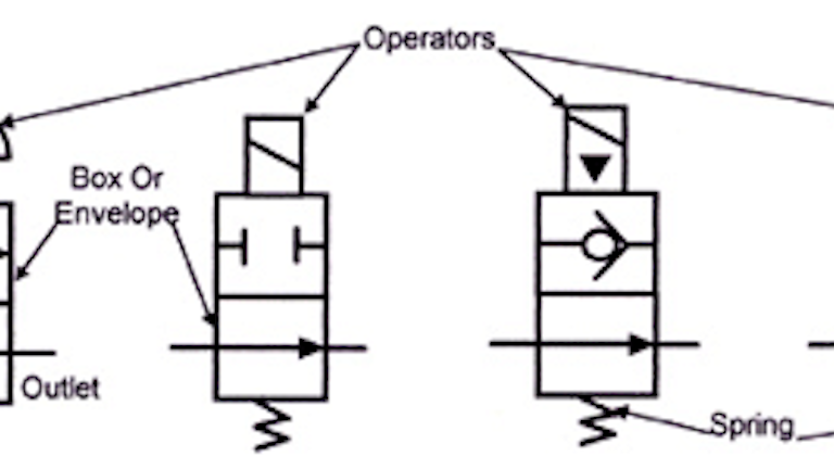
A 52 valve schematic will be illustrated with 2 blocks describing two valve functions or positions a 53 valve schematic will show three blocks describing 3 possible valve functions. Electra cloud page 1 all changes saved still hitting on that save button every 15 seconds. Valve symbols including solenoid valve symbols are those that are in common use. Solenoid valve symbols solenoid valve and common pneumatic system symbols.
Recognizing and understanding schematic symbols will enable you to comprehend a circuits function. Solenoid iec symbols. The open and closed state are again displayed with two rectangular squares. It reveals the elements of the circuit as simplified forms as well as the power as well as signal connections between the devices.
The schematic diagram is usually applied to the pneumatic system design and product identifications for pneumatic system designers and solenoid valve users to get a thorough understanding of product functions. Assortment of solenoid valve wiring schematic. A significant voltage drop between the power supply and solenoid may occur if there is unexpected resistance such as long lead wires or other electrical components. Schematic symbols are used to identify and graphically depict the function of fluid power components.
The solenoid valve symbols are the schematic diagram used to describe functions of the solenoid valve. Learn more sign me up electra cloud is the next generation cloud based electrical schematic software with built in versioning. The recommended lfix1002350a schematic includes an h bridge chip which reverses the direction of current flow allowing for effective latching solenoid valve switching. Use electra cloud with built in version control learn more sign me up electra cloud page 1 all changes saved still hitting that save button every 15 seconds.
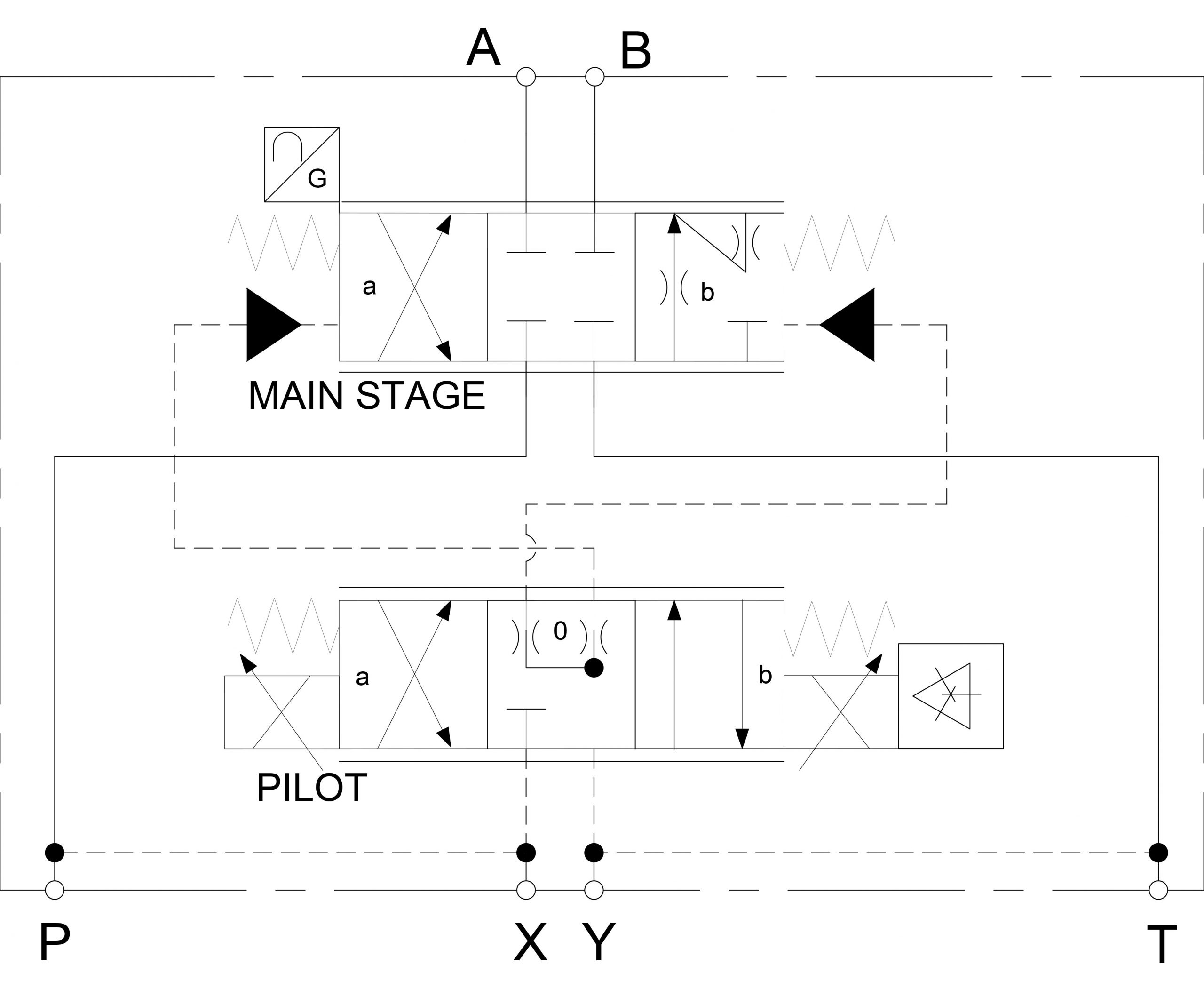
Hydraulic Symbology 302 High Response Valves
Using Graphic Symbols To Illustrate Basic Circuit Designs Ppt
Book 2 Chapter 8 Directional Control Valves Hydraulics

Razor Electric Scooter Wiring Diagram Also Contactor Relay Wiring
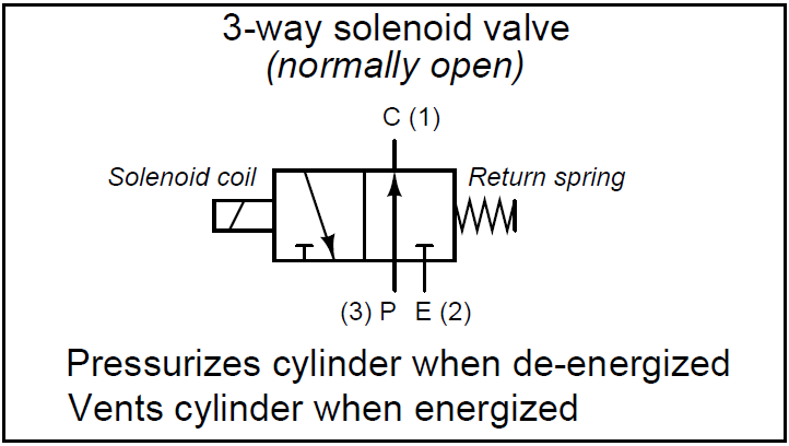
What Is A 3 Way Solenoid Valve Instrumentation Tools

The Solenoid Valve Circuit Of Internal Wiring Download
Solenoid Valve Symbols
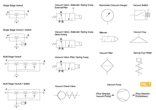
Basic Vacuum Schematics Fluid Power Journal

How A 3 2 Way Pneumatic Valve Works A Buying Guide Tameson
