Electronic Ballast Schematic
Energy Saving Lamp Electronic Ballast Circuit Under Other Circuits
Compact Fluorescent Lamp

175w Mercury Vapor Lamp Auto On Or Off Electronic Ballast Circuit
Here you also find the block diagram of electronic ballast which will help you too much to understand the electronic ballast circuit.

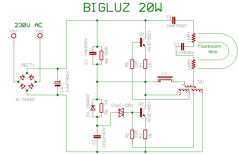
Electronic ballast schematic. Diodes d 8 d 9 d 5 d 6 clamp the output voltage values within the supply rails. A familiar and widely used example is the inductive ballast used in fluorescent lamps to limit the current through the tube which would otherwise rise to a destructive level due to the negative differential resistance of the tubes voltage current characteristic. A wiring diagram is a simplified standard pictorial representation of an electrical circuit. The typical electronic ballast is a current fed oscillator in the half bridge configuration.
A 2x54wt5 ballast with active pfc is designed around the irs2580d combo8 pfcballast control ic. 40 watt electronic ballast circuit last updated on august 29 2019 by swagatam 102 comments the proposed 40 watt electronic ballast is designed to illuminate any 40 watt fluorescent tube with high efficiency and optimal brightness. Electronic ballast circuit diagram with the explanation of the working principle. Newer electronic ballasts are usually wired in parallel except for rapid start programmed start and dimmable ballasts.
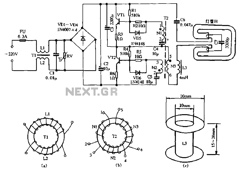
Electronic fluorescent lamp ballast by a. It reveals the parts of the circuit as simplified forms as well as the power and also signal links in between the devices. Transistors t 1 t 2 and capacitors c 5 c 6 form the half bridge in the circuit electronic ballast for tube light. Blocks any electromagnetic interference rectifier.
In operation a voltage is applied. The magnetic ballast uses a core and coil assembly transformer that provides a minimum functions of starting and operating the lamp. Introduction fluorescent lamps have applications in most areas of lighting where they give longer lifetime and lower power consumption for equivalent light output compared to filament bulbs with the disadvantage of higher initial cost. 5 26w electronic ballast circuit schematic.
Diodes d 1 to d 4 and capacitors c 1 to c 3 provide the required dc voltage for the circuit. The basic components used in the electronic ballast are listed below. Converts ac power to dc power pfc. It does power factor correction half bridge resonant output.
Here i have given the circuit diagram of electronic ballast with proper indication and explained each part of the circuit. In present days electronic ballast design is so robust and somewhat complicated to work very smoothly with high leveled controlling ability. An electrical ballast is a device placed in series with a load to limit the amount of current in an electrical circuit. The circuit includes figure 6 the control for both the boost pfc and the half bridge resonant stages.
Hence it is not as efficient as the electronic ballast. The boost pfc circuit is controlled by the vs and pfc pins of the ic. Collection of electronic ballast wiring diagram.

High Power Electronic Ballasts For Medium Pressure Uv Lamps
How Fluorescent Lamps Work

Dimmable Screw In Compact Fluorescent Lamp Having Integral

Dimmable Screw In Compact Fluorescent Lamp Having Integral
Electronic Ballast Images Electronic Ballast Transparent Png

Electronic Ballast

Electronic Ballasts
Various Schematics And Diagrams

Electronic Ballast 8 Steps Instructables
