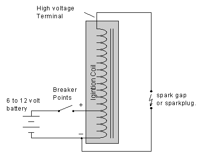
Engine Coil Diagram
Current flows from the battery through the primary winding of the coil.

Engine coil diagram. Dec 10 2016 automotive wiring diagram resistor to coil connect to distributor wiring diagram for ignition coil. Combustion engines like the one in your lawn mower require a spark to ignite the fuel the engine needs for operation. An ignition coil also called a spark coil is an induction coil in an automobiles ignition system that transforms the batterys low voltage to the thousands of volts needed to create an electric spark in the spark plugs to ignite the fuel. Most coils have.
Wiring diagram for ignition coil. Wrapped around it is the secondary coil. Be sure to unhook the coil from the equipment wiring harness as well as the engines wiring harness and use the spark tester. Coils on older model cars or those made before 1980 were controlled by a mechanical switch commonly called points.
This video concentrates on coils from an electronic point of view and reading wiring diagrams. We have labeled interactive exploded diagrams of power equipment from many of the top manufacturers. One coil of wire is called the primary coil. Parts lookup from jacks small engines.
Common mistakes when testing coils. An engine coil is used to produce the high voltage needed to fire the spark plugs on an internal combustion engine. The secondary coil normally has hundreds of times more turns of wire than the primary coil. Many a technician is fooled into replacing a good coil because the coil grounding lead was shorting out against a piece of sheet metal.
That spark is delivered by an ignition coil sometimes called a magneto. Some coils have an internal resistor while others rely on a resistor wire or an external resistor to limit the current flowing into the coil from the car.