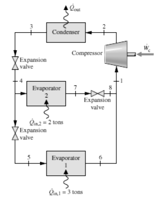
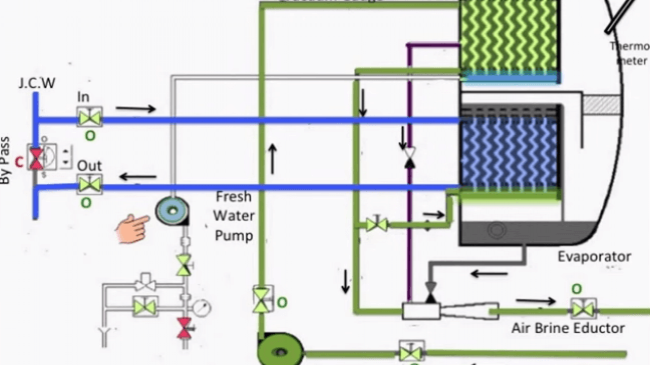
Evaporator Schematic
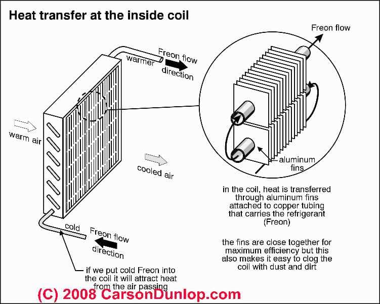
There will be relatively warm air flowing over the evaporator coil lets say about 80 degrees.

Evaporator schematic. That is called an air conditioning system ac or refrigeration system to allow a compressed cooling chemical such as r 22 freon or r 410a to evaporatevaporize from liquid to gas within the system while absorbing heat from the enclosed cooled area for example a. A rotary evaporator or rotavap rotovap is a device used in chemical laboratories for the efficient and gentle removal of solvents from samples by evaporationwhen referenced in the chemistry research literature description of the use of this technique and equipment may include the phrase rotary evaporator though use is often rather signaled by other language eg the sample was. The air conditiong system is designed so that the refrigerant will evaporate in the evaporator at a temperature of about 40 degrees so that it will be cold compared to the warm air flowing over it. Refer to wiring schematic shipped on units for unit wiring.
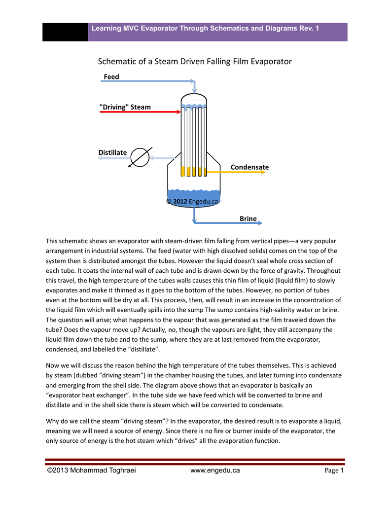
This is a drawback in the treatment of heat sensitive products. Wiring diagram cold room information about schematics pdf. In a falling film evaporator weak liquor is pumped to the top of the unit and distributed to the tubes where it runs down as a film. Schematics in this installation operation manual are typical wiring schematics only.
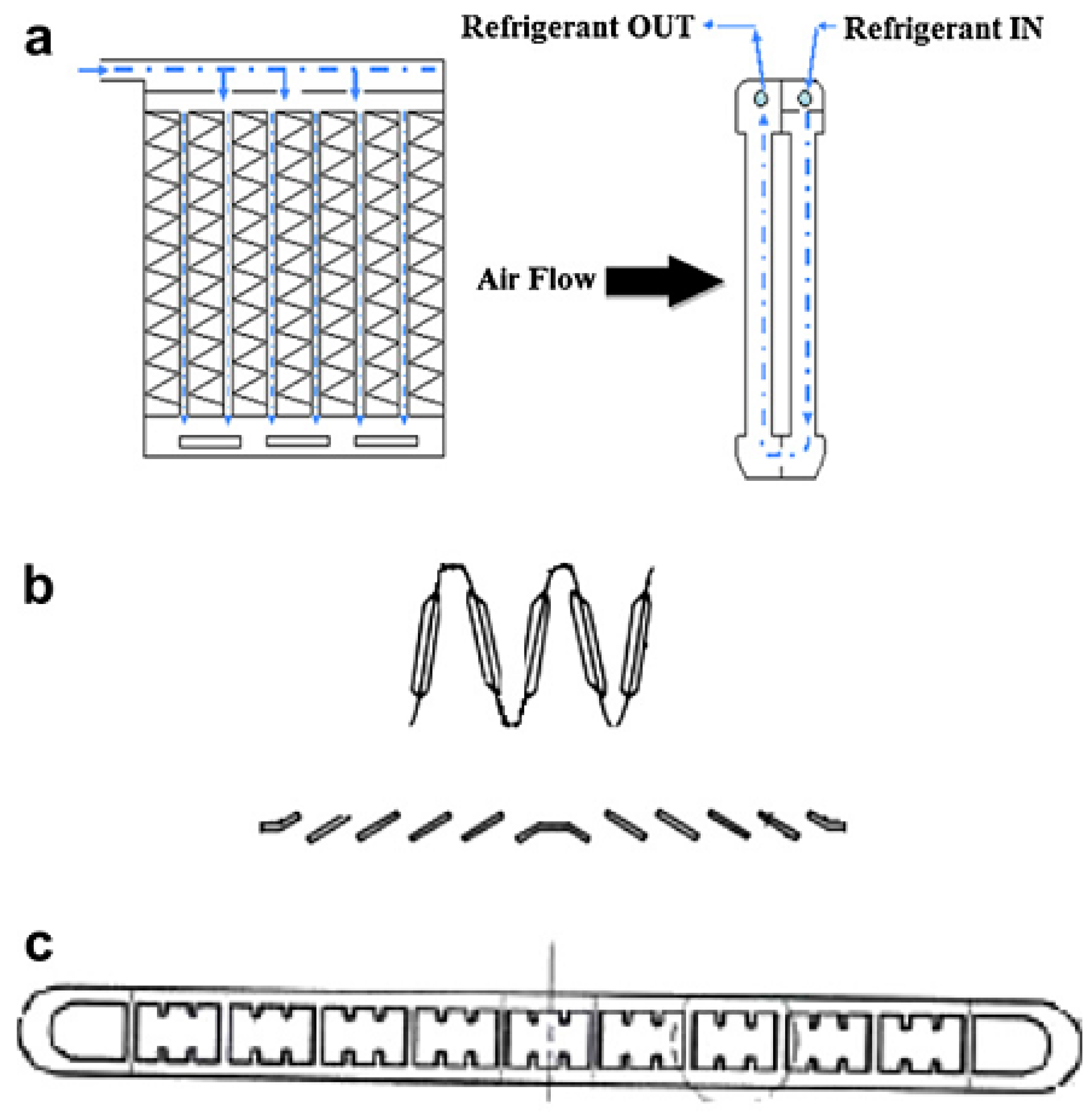
Evaporator schematic diagram download scientific diagram pdf. 2 972 how a compression refrigeration system works pdf. One kind of evaporator is a kind of radiator coil used in a closed compressor driven circulation of a liquid coolant. The falling film evaporator is used for liquor concentration.
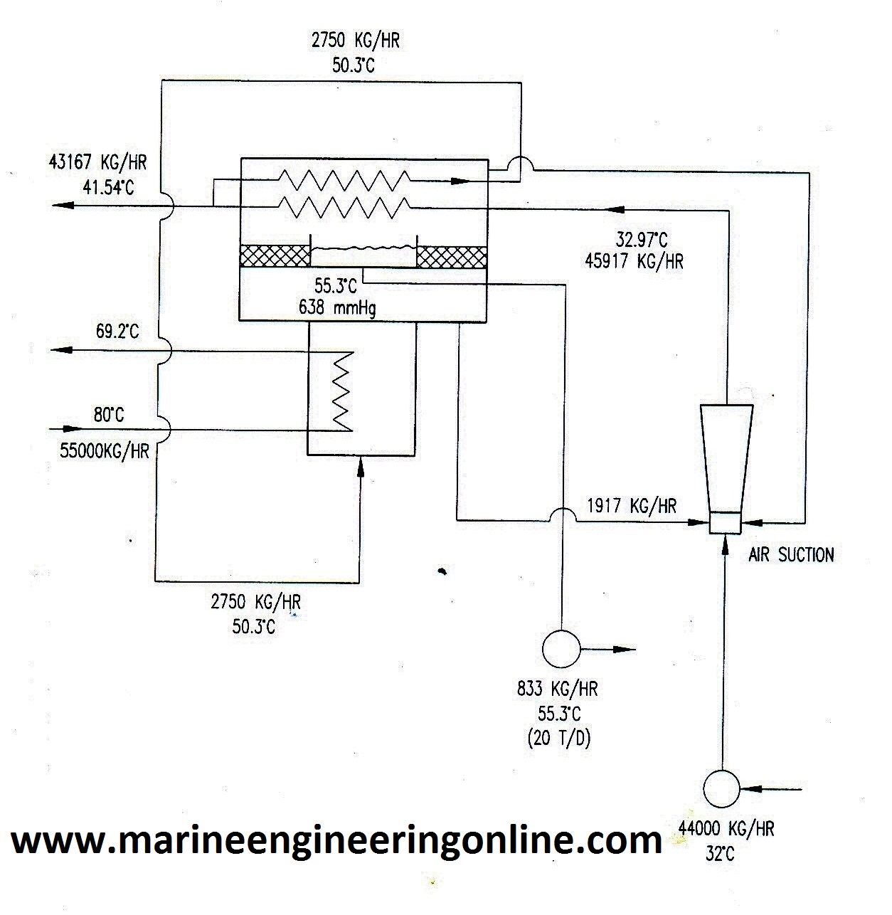
When a liquid is heated it begins to boil as the liquid turns to vapor forming. And that brings us to the evaporator component 4 in the air conditioning circuit and cycle diagram. A schematic of the unit operation and its inlets and outlet are found in the next heading under diagram. The image on the left shows a small split system for a walk in cooler with 3 electrical devices.
2005 f150 evaporator diagram wiring diagram images gallery pdf. Transformer is in each evaporator the voltage tap must be set on each evaporator. Those 3 electrical devices are represented on the ladder schematic shown below. The feed water with high dissolved solids comes on the top of the system then is distributed amongst the tubes.
First we need to know what loads there are to be controlled. Program all slave evaporators as slaves. A compressor condenser fan motor and evaporator fan motor. This schematic shows an evaporator with steam driven film falling from vertical pipesa very popular arrangement in industrial systems.
Evaporators are shipped from our factory with a. However evaporators with four to seven effects and additional finishers have been used in the dairy industry for a long time now in order to save energy.

