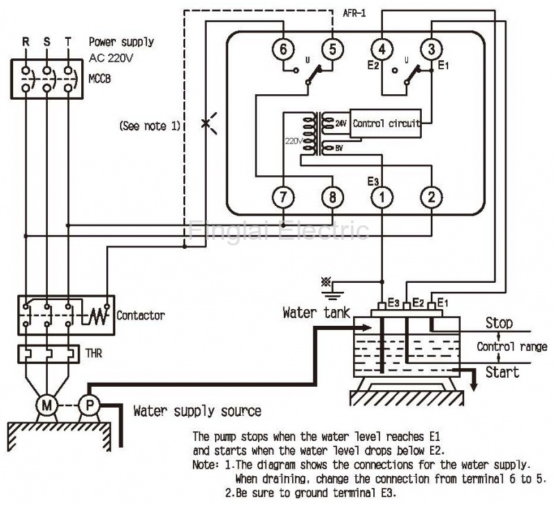
Float Switch Wiring Diagram Pdf
Float switches of the 21st century have come much further in the amount of operations your float switch can perform.

Float switch wiring diagram pdf. This float switch is rated to directly control motors of up to horsepower or 13 amps at 120 or 220 volts ac for non continuous pump operations and up to 13 amps dc for motor loads. Thank you for your float switch purchase. In both of these applications the black wire is connected to the ac neutral supply and the brown wire is connected to the pump relay or valve neutral input. Always remember to disconnect all power and have your float switch installed by a licensed electrician.
When the tank is low on water the oat switch activates the pump motor and turns a red pilot light on. The pump is used to ll a tank with water. Make sure you seal the cable entrance with a cable gland. Water level controls new float switches work by using probes instead of floats to detect or sense.
Wiring diagram for float switch on a bilge pump amazon shoreline marine bilge pump float switch the shoreline bilge pump float switch is an automatic lever type switch no mercury with tinned marine grade wire for use with most 12 volt bilge pumps 10 and. Wiring a float switch isnt necessarily hard but it can be a little confusing if you dont have a visual aid or two. We require a whole new idea for it and one of them is this rule float switch wiring. Once youve figured out the weight position and your switching levels youll need to install float switch wiring to your waterproof enclosure.
Remember that what youre wiring is a means of turning things on and off. Float switch control of a pump and pilot lights in circuit 3 a oat switch is used to operate a pump motor. The float switch cord is secured at the desired low water level threshold. For wiring instructions refer to the user manual or our new float switch wiring guide.