Fluorescent Wiring Diagram
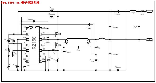
Ir2156 Fluorescent Lamp Integrated Circuit Electron Ballast

Wjr709ttqf65sm

Wiring Diagram Of Three Control Switch Page 1 Line 17qq Com
The arc within the lamp may generate radio frequency noise which can be conducted through power wiring.

Fluorescent wiring diagram. It reveals the components of the circuit as streamlined shapes and also the power as well as signal connections between the devices. Buy your fluorescent t8 ballasts at. Very good suppression is possible but adds to the cost of the fluorescent fixtures. Fluorescent lamps are a non linear load and generate harmonic currents in the electrical power supply.
It reveals the components of the circuit as streamlined forms and the power and also signal links in between the gadgets. A wiring diagram is a streamlined standard pictorial representation of an electric circuit. Watch as total bulk lighting provides an overview of the fluorescent t8 ballast and what all those wires mean. Suppression of radio interference is possible.
It actually is a lot simpler than then you think. The wiring process of fluorescent tube lamplight with ballast starter is quite easy and simple. A fluorescent tube circuit includes a ballast wires lampholders and the tubes. This post fluorescent light wiring diagram tube light circuit is about how to wiring fluorescent light and how a fluorescent tube light works.
A wiring diagram is a streamlined traditional photographic representation of an electric circuit. How to install a single tube light with electromagnetic ballast from the junction box the neutral wire is not taken out to the switch board rather it is taken out from the junction box and carried out to the port 2 of the tube light as per figure above. Ballast wiring diagram shows how the ballast is wired to the lamps ballast wiring diagram. Collection of led fluorescent tube replacement wiring diagram.
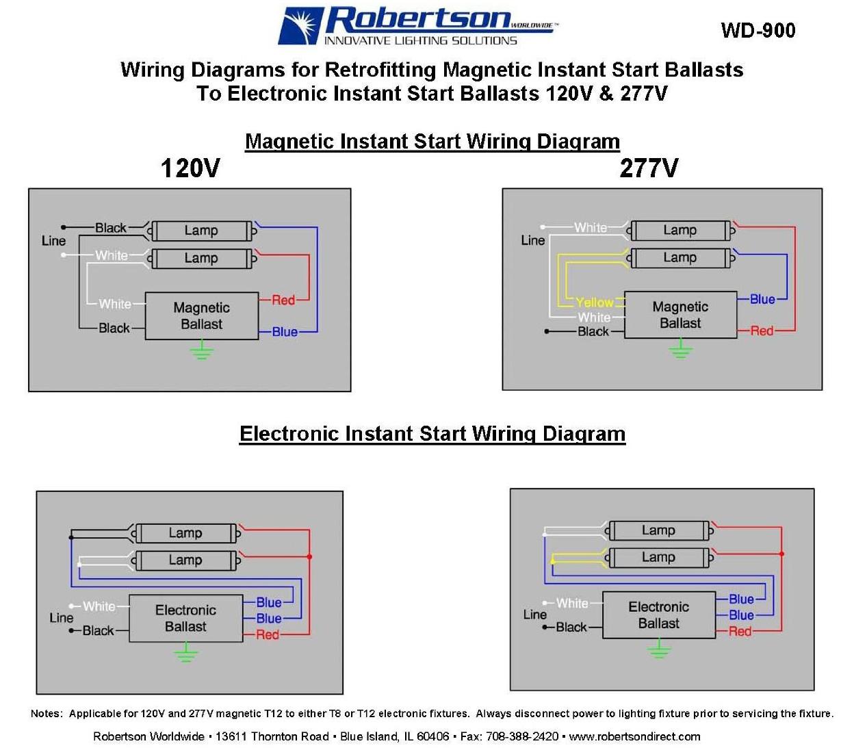
Changing the wiring on a fluorescent light fixture from series to parallel. Variety of convert fluorescent to led wiring diagram. Different electrical symbols are used to make the wiring diagram below. Newer fluorescent ballasts are usually rated for both 120 volts and 277 volts.
Parallel ballasts can only be wired in parallel according to the diagram on the ballast. A wiring diagram is a simplified standard photographic depiction of an electric circuit. In most cases when we buy a fluorescent light it comes in a complete set with all wire connected.

Electrical Ballast Wiring Diagram Electronics Electrical Wires

Wazipoint Engineering Science Technology Tube Light Wiring

Emergency Exit Sign Wiring Diagram Diagram Base Website Wiring
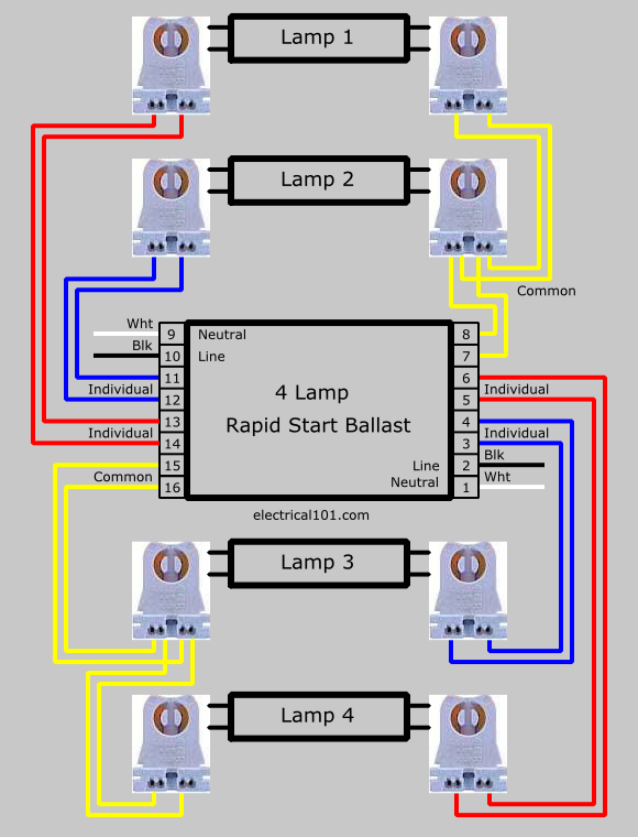
Series Ballast Lampholder Wiring 2 And 4 Lamps Electrical 101

E78d Wh5 120 L Wiring Diagram Wiring Library

Dv 6626 Ballast Wiring Diagram As Well Ge Proline T12 Ballast
Bb2 2l T12 Ballast Wiring Diagram Wiring Library
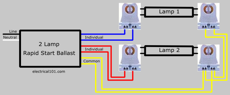
Series Ballast Lampholder Wiring 2 And 4 Lamps Electrical 101
2328b7 Emergency Lighting Ballast Wiring Diagram Wiring Library
