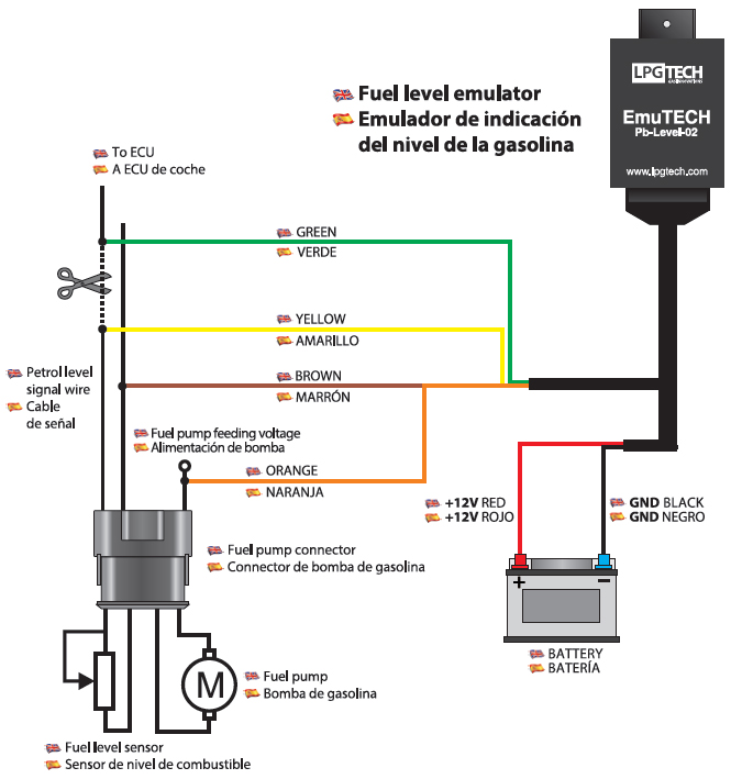
Fuel Level Sensor Wiring Diagram
Pressure sensor wiring diagram amazon printed books https.

Fuel level sensor wiring diagram. There are two types of sending units. Fuel sending unit wiring diagram volovetsfo. Electric fuel sender wiring diagram wire center wiring diagram. Parts of the fuel level sender unit to be ad fuel level sender installation.
We believe this wema fuel gauge wiring diagram photo could possibly be the most trending topic. Measure the depth of your fuel tank. Automotive wiring diagram worksheet inspirationa fuel gauge sending. P0463 fuel level sensor circuit signal highopen trouble code.
The fuel sending unit is responsible for what the fuel gauge on your vehicle reads. Fozmulas comprehensive range of fuel level senders and sensors enables customers to monitor fuel level continuously on applications including generator sets pumps commercial passenger service off highway and defence vehicles. Install the new gauge reconnect the wiring and turn on the power. The older float style which uses a magnet embedded in a float that resides in a tube sending readings of how high in the tank it is floating and there is the newer style that measures electrical resistance of the volume of fuel in the tank.
S for the sender g or for the ground and i for the ignition. In this video i will show you how to test a fuel tank sending unit float. The unit can be adjusted to read accurately in tanks from 6 to 23 deep. Fuel rail pressure sensor signal voltage low pull up type duration.
Check the wiring diagram that comes with the kit and mark the back of the new fuel gauge with symbols for each post. Refer to the vdo catalog for matching fuel gauges. Typically the spring loaded fingers that ride on the.