Functional Block Diagram Of Plc

Https Encrypted Tbn0 Gstatic Com Images Q Tbn 3aand9gctza68e Irkzmneeqgsilllte9xvv7nik9eckzxyckgpdqt3it4 Usqp Cau

Functional Block Diagram Of Proposed System V Working Gate

Programmable Logic Controllers Plcs Basics Types
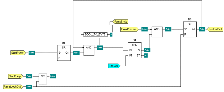
Inputs and outputs of the blocks are wired together with connection lines or links.

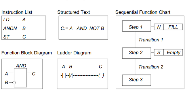
Functional block diagram of plc. Function block diagram is easy to learn and provides a lot of possibilities. It is a simple and graphical way to program any functions together in a plc program. The function block diagram fbd is a graphical language for programmable logic controller design that can describe the function between input variables and output variables. Plc designers introduced specialised intelligent units for the various tasks to be carried out by logic controllers but multiprocessing still greatly increases the complexity of system programming.
Graphic languages ladder diagram and function block diagram annex a. Specifically what they are and when do we use them when programming plcs. In a function block diagram the entire rung is replaced by this box or block. Guidance on selection installation and maintenance of plcs.
2 overview of the function block diagram language. The connecting lines will have a compatible information type at both ends. List of major changes and extensions of the third edition. If you have found this blog post chances are you have heard of either ladder logic function block diagrams or both.
A functional block diagram describes a function between input and output through a functional block. A large metal press brake uses and logic for its controls. A function is described as a set of elementary blocks. Many industrial machine use and logic.
One of the official and widely used plc programming languages is the function block diagram fbd. Input and output variables are connected to blocks by connection lines. The term function block diagram fbd is used for plc programs described in terms of graphical blocks. This chapter is an introduction to the programming of a plc using ladder diagrams and functional block diagrams with discussion of the other techniques in the next chapter.
Tambe assistant professor department of electronics engineering walchand institute of technology solapur. It is described as a graphical language for depicting signal and data flows through blocks which are reusable software elements. Formal specification of the language elements.
Beckhoff Information System English

Function Block Diagram Fbd Programming Tutorial With Images

Plc Experion Programming Code For Flc As Functional Block Diagram

Bachmann Electronic Gmbh Programming With Function Blocks
Solved Submit The Assignment On Or Before 20 4 2020 1 Dra
What Are Iec 61131 3 And Plcopen

Plc Learning Series 7 Functional Block Diagram Program Symbols

Fmea Functional Block Diagram Download Scientific Diagram
An Overview Of Software Languages For Programmable Logic
