Graphic Equalizer Schematic
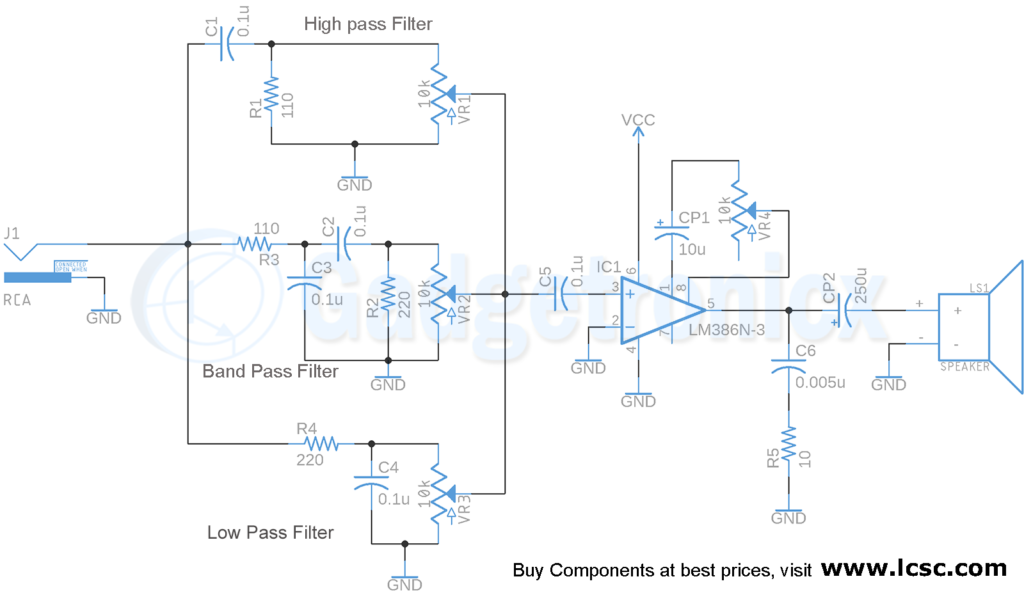
2 Channel Audio Equalizer Circuit Gadgetronicx
1592001248000000
Transistor Equalizer Circuit Diagram
It has no coil.
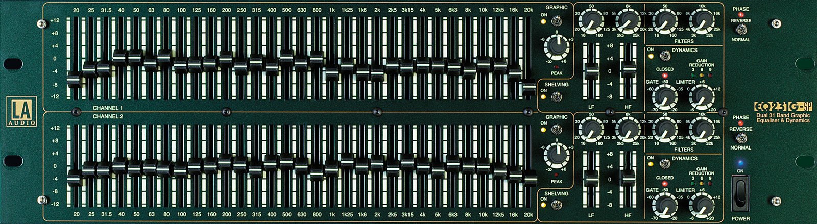
Graphic equalizer schematic. Software equalizers work but it can be challenging to find one that is easy to use for all platforms especially mobile platforms. Here the 20 band graphic equalizer schematic diagram. This project has both a battery so you can take it on the go in addition to a dc jack to draw power from an external source. The circuit can be easily converted to a 5 band graphic equalizer by simply eliminating 5 stages from the shown design.
This equalizer is has simple design and easy to construct. It has no coil. The graphic equalizer consists of an input buffer ic1 a a variable boost cut active filter lc2 a and an output summing amplifier ic1 b. It has no coil.
This reference design features a 1 octave or 10 band stereo graphic equalizer. Here the 20 band graphic equalizer schematic diagram. All one has to do is feed the tv or pc audio input to this circuit and hook the output with the existing home theater amplifier. The cut frequency can be adjusted using variable resistors.
Here the 20 band graphic equalizer schematic diagram. With graphic equalizer we make selective cutting off or boost of selected departments of acoustic spectrum. The battery is automatically disconnected when the dc jack. Tl074 10 band graphic equalizer.
Circuit of graphic equalizer of 7 bands using it integrated la3607 of sanyo. Graphic equalizer using 4558 lf353. This is stereo graphic equalizer it should be 210 channel equalizer. The circuit integrated la3607 allows to just set up a graphic equalizer of 7 bands for a channel adding some capacitors and variable resistors to the circuit.
A graphic equalizer is an audio equipment that is used to compensate for irregularities in the listening environment or to match the sound to the listeners taste. The ic1 a circuit is designed for unity gain and is used mainly for impedance matching between the input source and the equalizer filters. Graphic equalizers device are popular with both domestic users and professional users. With this way we can adapt the musical reproduction in the characteristics of space where we hear.
Graphic equalizers device are popular with both domestic users and professional users. I decided to build this project as a way to have easy control over musics tone. The unit is quite simple to use. Graphic equalizers device are popular with both domestic users and professional users.
This equalizer is has simple design and easy to construct. This graphic equalizer circuit using op amp 4558 lf353 circuit 5 channels 2 octave graphic equaliser easy to make equalizer because using ic 4558 or lm1458 or lf353 nice if you are seeking graphic equalizer circuit at can fine decorate the sound of music has full frequency sound section. This is stereo graphic equalizer it should be 210 channel equalizer.
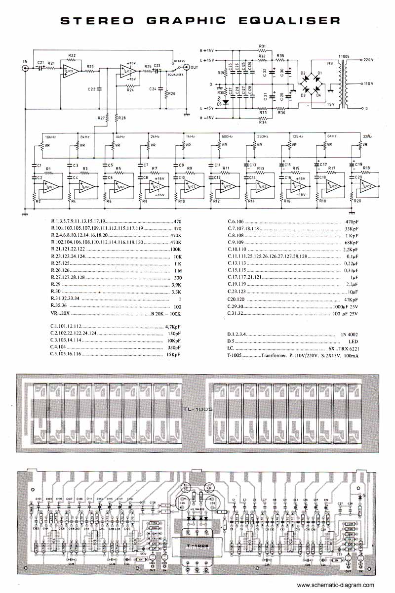
2 X 10 Band Stereo Graphic Equaliser Electronic Schematic Diagram
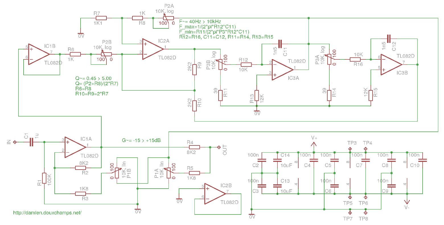
Parametric Audio Equalizer
Contents Graphic Equalizer Goldhand
Parametric Eq Vs Graphic Eq Sound Schematic
100 Watt Hifi Amplifier Circuit And 5 Band Equalizer Electronics
Experimentalists Anonymous Diy Archives

Tv 4482 5 Band Graphic Equalizer Using La3600 Free Diagram
6 Band Graphic Equalizer Simple Circuit Diagram

Schematics Com Search Results
