Heat Engine Diagram
Heat Engines And The Second Law

Volcanoes As Heat Engines

Slide2
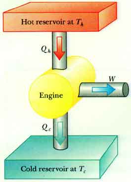
Q c is waste heat going into the cold sink.

Heat engine diagram. Of an engine is express as its efficiency. The area inside the loop is a representation of the amount of work done during a cycle. Let us derive an expression for the efficiency of a. Heat engine took q2 amount of heat from the hot body and did work equivalent to w e.
It takes heat from a reservoir then does some work like moving a piston lifting weight etc and finally discharging some of the heat energy into the sink. Schematically it can be represented as. Heat is transferred from the source through working fluid in the heat engine and into the sink and in this process some of the heat is converted into work. The heat supplied to sink is equal to q1.
A machine that converts heat energy into work by shuttling back and forth between a high temperature and a lower one. Of heat engine refrigerator and heat pump is discussed below heat engine fig a shows a schematic diagram of the heat engine. A heat engine is a device that converts heat to work. For a cyclic heat engine process the pv diagram will be a closed loop.
Heat engines enable heat energy to be converted to kinetic energy through the medium of a working fluid. In thermodynamics heat engines are often modeled using a standard engineering model such as the otto cyclethe theoretical model can be refined and augmented with actual data from an operating engine using tools such as an indicator diagramsince very few actual implementations of heat engines exactly match their underlying thermodynamic cycles one could say that a thermodynamic. Carnot engine diagram modern where an amount of heat q h flows from a high temperature t h furnace through the fluid of the working body working substance and the remaining heat q c flows into the cold sink t c thus forcing the working substance to do mechanical work w on the surroundings via cycles of contractions and expansions. The basic concept of a heat engine.
The heat engine as part of a system. T h is the heat source and t c the cold sink. The diagram opposite shows the system heat flow. W is the useful work coming out of the engine.
When scientists study heat engines they come up with ideas. A typical heat engine is powered by burning fuel lower left and uses an expanding contracting piston upper center to carry the fuels energy to a spinning wheel lower right.
Heat Engines
Heat Engines
Thermodynamics

Enso Heat Engine Shifts Eastward Under Global Warming Eurekalert
General Physics Ii
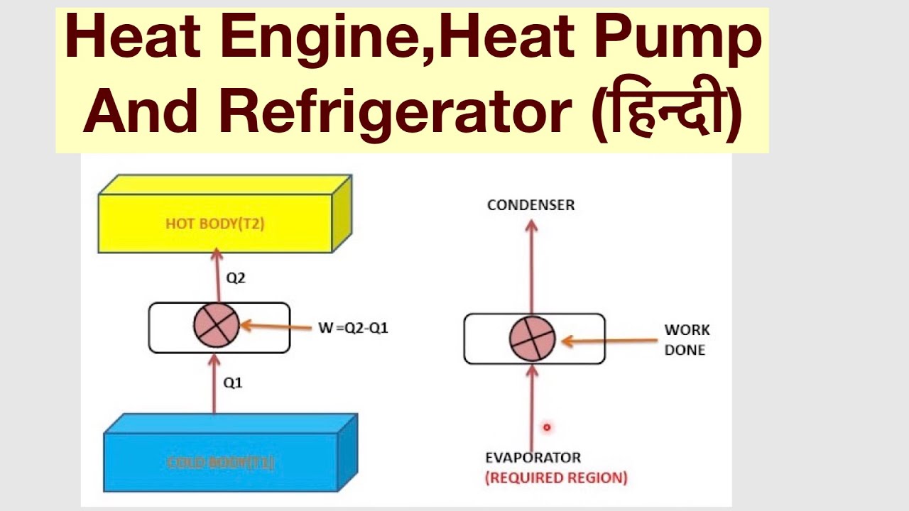
Heat Engine Heat Pump And Refrigerator Understand Easily
Thermodynamic Picture Of A Heat Engine Download Scientific Diagram
Https Encrypted Tbn0 Gstatic Com Images Q Tbn 3aand9gcs5iatm7vq2l7flzqqq89fk1e Aofim2zprrfmktbjmqsxpnbrs47lkqrtqmpz7y9a Usqp Cau
What Is Heat Engine Classification Of Heat Engines Extrudesign
