House Thermostat Wiring Diagram
Can T Control The Heat When Switched From The Thermostat E To 3rd

Heat Pump Thermostat

Wiring Diagram For Thermostat
A wiring diagram is a streamlined standard photographic representation of an electric circuit.

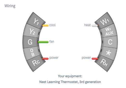
House thermostat wiring diagram. Thermostat wiring diagrams for heat pumps heat pump thermostat wire diagrams. Heck now im not calling anyone a dummy. If you check the honeywell thermostat ct31a1003 wiring diagram youll see that it requires only two wires. By the use of an adjustable set point the job of the thermostat is to turn on either the heating or cooling system to maintain the desired room temperature in the home and to turn off the system when the desired temperature is achieved.
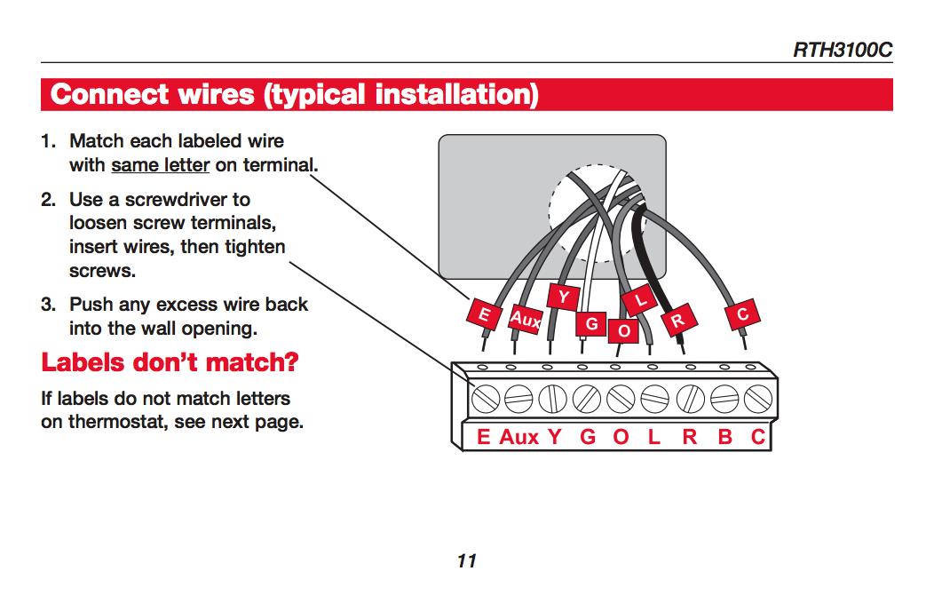
A starting with the c wire match the sticky tag on the wire to the terminal labels. The main trouble is dealing with those different colored wires knowing which one does what and if that wasnt enough. Thermostat wiring for dummies. Richard lloyd 2653109 views.
Even the most seasoned people who enjoy diy may come across problems with wiring a thermostat. All you want to know about the thermostat wiring are available in our post that the most significant matter is that the diagrams and wiring colorwiring conventional system 7a wire the wi fi thermostat to your conventional system. To wire a thermostat you must first be aware of the type of system that you have in your home. Heat pumps are different than air conditioners because a heat pump uses the process of refrigeration to heat and coolwhile an air conditioner uses the process of refrigeration to only cool the central air conditioner will usually be paired with a gas furnace an electric furnace or some other method of heating.
The thermostat is the control device that provides a simple user interface with the internal workings of your homes climate control system. House thermostat wiring diagram a novice s guide to circuit diagrams. Collection of house thermostat wiring diagram. It reveals the parts of the circuit as simplified forms as well as the power and signal links in between the devices.
This is because its a very basic thermostat designed only to control a heating system. The thermostat wiring on these systems can have very similar wiring properties. A very first look at a circuit representation might be confusing however if you can review a subway map you could check out schematics. Ac fancompressor not working how to test repair broken hvac run start capacitor air condition hd duration.
A large majority of homes today have an hvac system containing a furnace oil gas or electric and an ac unit. My paperback and e book.

House Thermostat Wiring Diagram Thermostat Wiring Hvac
How Wire A Honeywell Room Thermostat Honeywell Thermostat Wiring
6 Wire Thermostat Wiring Diagram

Thermostat Wiring Explained

Control A 3 Wire Zone Valve With A 2 Wire Thermostat Geek Wisdom
1591862263000000

Central Heating Electrical Wiring Part 3 Y Plan Youtube

Https Encrypted Tbn0 Gstatic Com Images Q Tbn 3aand9gcslax4mazt1wnunbwphjtvhlkr2bvvlk3kn4i9caefggy Gku45 Usqp Cau

Ecobee3 Wiring Diagrams Ecobee Support
