How To Make A Functional Block Diagram
Lines connecting the blocks will show the relationship between these components.

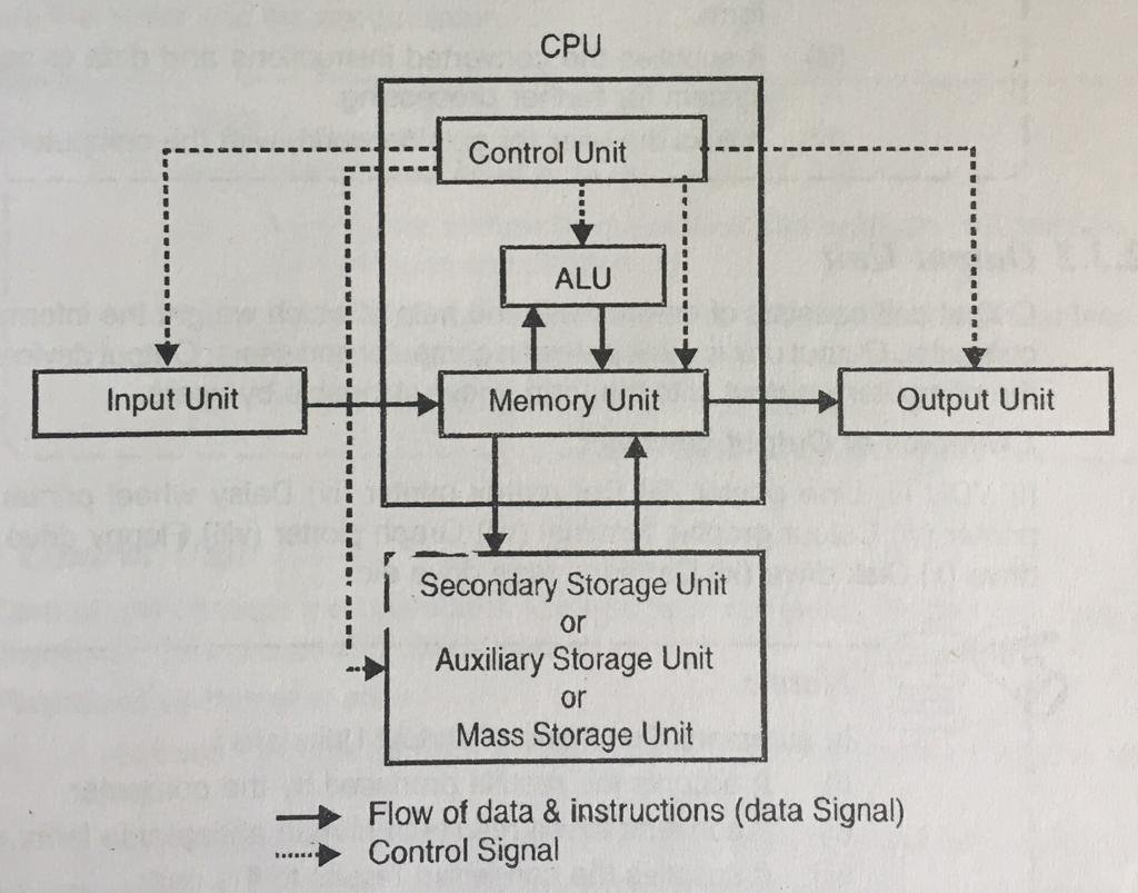
How to make a functional block diagram. Functions of a system pictured by blocks. As you add shapes they will connect and remain connected even if you need to move or delete items. The functional block diagram which is a type of the block diagrams can be represented as a combination of an ordinary functional block diagram and a flow chart at the same time. A block diagram is a specialized flowchart used in engineering to visualize a system at a high level.
The functional block diagram can picture. You can use one of so many different specific functional block diagrams technics in order to build different software development methodologies. You will want to create blocks often represented by rectangular shapes that represent important points of interest in the system from input to output. Function block diagram is easy to learn and provides a lot of possibilities.
Here functional flow pertains to the sequencing of operations with flow arrows expressing. It is a great way to implement everything from logic to timers pid controllers and even a scada system in your solution etc. The term functional in this context is different from its use in functional programming or in mathematics where pairing functional with flow would be ambiguous. Input and output elements of a block pictured with lines.
A functional flow block diagram ffbd is a multi tier time sequenced step by step flow diagram of a systems functional flow. A variety of commonly used shapes and connecting lines rules of construction and actions pertaining to them make block diagram a versatile and flexible tool for many forms of industry. Block diagrams are made similar to flowcharts. Block diagrams are essentially a very simple format of diagrams.
Smartdraw helps you make block diagrams easily with built in automation and block diagram templates.