Hvac Control Board Wiring Diagram

Thermostat Wiring Colors Code Easy Hvac Wire Color Details

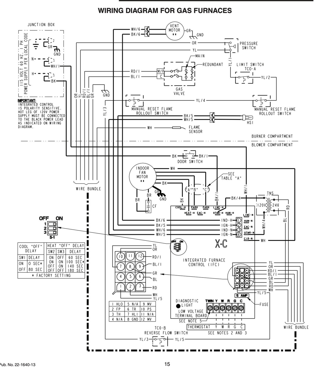
Lennox Furnace Control Board Wiring Diagram Diagram Base Website

Atwood Water Heater G6a 8e Esimnetogrosseet Site
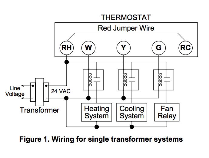
Furnace thermostat wiring diagram terminal letters on a thermostat and what they control the hot wire 24 volts usually red from the transformer is the main power wire to turn on or off a furnace components.
![]()
Hvac control board wiring diagram. Nortek global hvacreznor does not endorse any field changes to factory wiring schemes. Schematic diagrams schematic diagrams show components in their electrical sequence without regard for physical location. Therefore a splice is not needed. Furthermore some manufacturers put a terminal board strip near the control board in the air handler.
Control board 1 this diagram is to be used as reference for the low voltage control wiring of your heating and ac system. Electrical wiring diagrams for air conditioning systems part one. Thermostat wiring diagrams heat pumps are wired for hvac control far differently than air conditioning systems so make sure you know the difference and correctly identify the type of hvac system you have installed. In this video i show where all the wires go on this bryant furnace control board.
Hvac control board replacement duration. Wiring diagrams wiring diagrams show components mounted in their general location with connecting wires. Typically a thermostat wire pull is made to the air handler on split systems. Also note that certain field modifications may occur to accommodate the use of other control systems.
For example if the red wire is connected. This wire is then spliced for the separate wire pull which is made to the condenser. Hvac training videos blower motors blower control board trouble shooting air handler circuit board how to troubleshoot a blower board goodman blower board hvac blower board. Additionally before you decide to change your thermostat make sure you have the correct tools especially a screwdriver and wire pliers.
Gas furnace control board wiring diagram just whats wiring diagram. Schematic diagrams are used to troubleshoot and install control circuits. All servicing of product should be performed by a licensed contractor according to local and national code requirements. Schematics are generally easier to read and understand than wiring diagrams.
A wiring diagram is a type of schematic which makes use of abstract pictorial symbols to reveal all the interconnections of parts in a system. Yellow wire for y terminal. Both the furnace control board and the thermostat will usually have the same terminal letters. A wiring diagram is.
The above points can be fulfilled by understanding the electrical wiring diagram of individual hvac equipment and of the whole system also. Note some ac systems will have a blue wire with a pink stripe in place of the yellow or y wire.

E69f Rudd Gas Furnace Wiring Diagram Older Wiring Library
A6554 Coleman Furnace Circuit Board Wiring Diagram Wiring Resources

Thermostat Wiring Explained

On Board Diagnostic Wiring Diagram Front Body Control Module Fbcm

Condenser Wiring Diagram Wiring Diagram
Pu Cb04 Wiring Chart England S Stove Works Inc
2

Wrg 1887 Hvac Control Board Wiring
Honeywell L4064b Combination Fan And Limit Control How To Set The
