Hvac Fan Relay Wiring
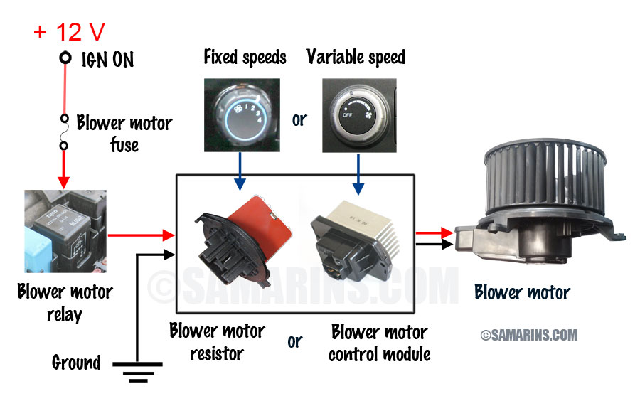
Blower Motor Resistor How It Works Symptoms Problems Testing

Goodman Hvac Fan Wiring Diagram Opo Aceh Tintenglueck De
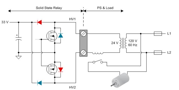
How To Power Your Thermostat Using Solid State Relays Industrial
Goettl las vegas air conditioning inc.

Hvac fan relay wiring. Variety of hvac fan relay wiring diagram. When a thermostat reaches a set temperature. Moreover the heat source for a basic ac system can include heat strips for electric heat or even a hot water coil inside the. I discuss more about spst spdt and spno spnc relays.
Furthermore on a split system the blower fan is in the air handler. Thermostat signals and color code. A wiring diagram is a simplified standard photographic depiction of an electrical circuit. In heating and cooling these relaycontactors are used to turn on high voltage components such as motors compressors and other high voltage components.
It reveals the elements of the circuit as simplified shapes and also the power and signal connections in between the devices. Understanding basic electrical wiring and components of air conditioning systems duration. Each component should be set and linked to different parts in particular manner. It takes at least two years of hvacr schooling to become qualified to learn.
Relays contactors are nothing more than a switch. G this is the terminal used for the fan relay to energize the indoor blower fan. Lack of standards makes this interesting. A wiring diagram is a streamlined conventional pictorial depiction of an electrical circuit.
Furthermore for the thermostat wiring colors code for this terminal if equipped consult with the installer or trace the wire out to the source. Your best bet is to see the manufacturers documentation both thermostat and hvac. I am having trouble wiring a blower motor to a fan relayhelp answered by a verified hvac technician. Do not try any of what you see in this video at home.
While there isnt an official standard for thermostat circuit wiring colors there is a general pattern. Otherwise the structure wont work as it should be. It reveals the parts of the circuit as streamlined shapes and the power as well as signal connections between the devices. By continuing to use this site you consent to the use of cookies on your device as described in our cookie policy unless you have disabled them.
How to wire an air conditioner for control 5 wires the diagram below includes the typical control wiring for a conventional central air conditioning systemfurthermore it includes a thermostat a condenser and an air handler with a heat source. We use cookies to give you the best possible experience on our website.

Hvac Relay Wiring Lupa Roti Salon Tres Nl

Hvac System Wiring Wiring Diagram
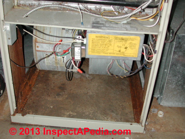
Furnace Or A C Blower Fan Won T Stop Running What To Check If The

462c4df Wiring Diagram Older Furnace Blower Relay Wiring Library

2b3 A C Condenser Contactor Wiring Wiring Library

Pin By Ashraf Ibrahim On Diy In 2020 Circuit Diagram Electrical
Vwvortex Com The X Circuit From The Ignition Switch

C Wire Issues Hacking Your Way To Become A Thermostat Wiring Pro

Basic Electrical Controls Of Air Conditioning Units Industrial
