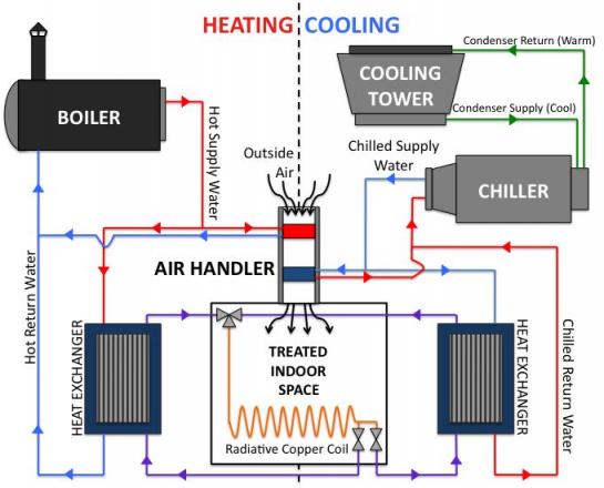
Hvac System Schematic Diagram

Sample Set 3 Design Drawings And Specifications For Residential

Hvac Schematic Diagram Mechanical Room Hvac Design Duct Work
Https Pdfs Semanticscholar Org 11c9 9a40a4ff55687ada3b9a2a3a9f25b04b9631 Pdf
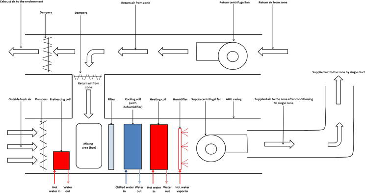
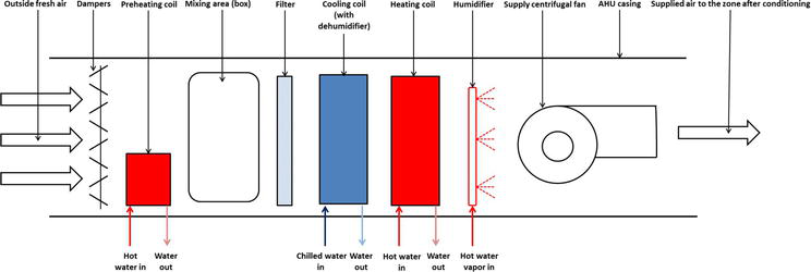
Air handling unit ahu.
Hvac system schematic diagram. Also the hvac designer will need to know the size of the electrical loads to assess the impact of the heat generated by the electrical system on the hvac load. A device used to condition and circulate air as part of a heating ventilating and air conditioning hvac system. The vav box is short for variable air volume box which is a type of hvac system. What you need to know if you know a little bit about home heating and cooling systems you probably realize that they are pretty complicated little systems.
The above points can be fulfilled by understanding the electrical wiring diagram of individual hvac equipment and of the whole system also. The organization of this module is based on a flow of concerns from basic principles to components to assemblies of components termed systems to applied examples of. Schematic diagrams for hvac systems. An air handler is usually a large metal box containing a blower heating or cooling elements filter racks or chambers sound attenuators and dampers.
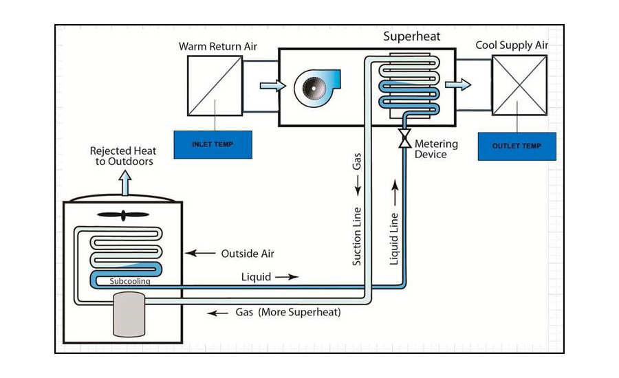
Inside those compact units are electrical connections fans compressors condensers switches coolantsthe list goes on and on. Goettl las vegas air conditioning inc. The metering device component 3 on this air conditioning circuit and cycle diagram is the dividing point between the high pressure and low pressure sides of the system and is designed to maintain a specific rate of flow of refrigerant into the low side of the system. A wiring diagram is used to represent how the circuit generally appears.
The temperature shape shows a kind of device to measure temperature. Hvac controls symbols the following hvac controls symbols include commonly used shapes that represent for measuring temperature flow velocity voltage current light timer power and more. Overseeing hvac system development from a broad building wide perspective the architect can and usually will leave the specifics of system design to consulting engineers. To help illustrate the differences between wiring diagrams and schematics a basic control circuit will first be explained as a schematic and then shown as a wiring diagram.
The Value Of Remote Residential Hvac Monitoring And Diagnostics
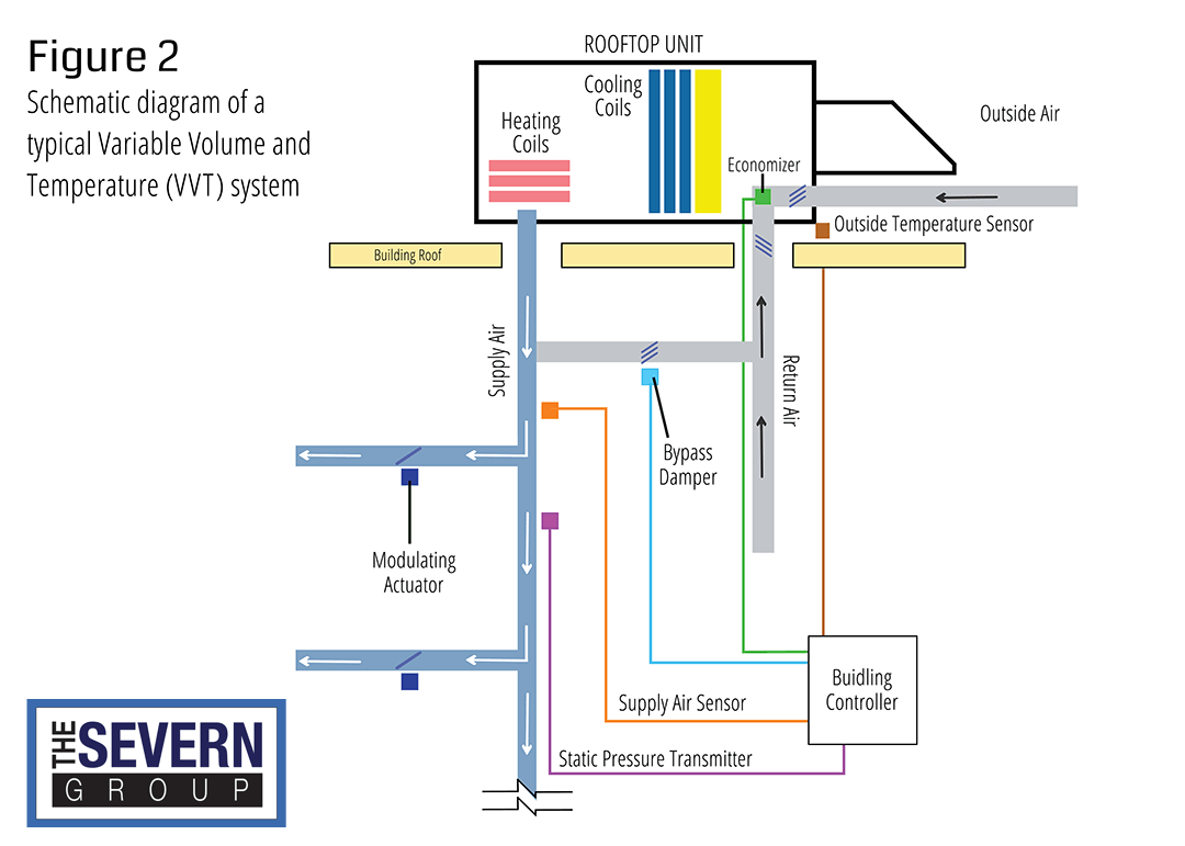
Vav Vs Vvt Hvac Systems The Severn Group
Central Air Conditioning Systems And Applications Intechopen

Facilities Utilities And Equipment In Images Ii

Automated Crowdsourced Power Outage Identification And Staggering
Cu Faculty

Trane Hvac System Wiring Diagram Wiring Diagram
2
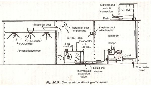
Direct Expansion Dx Type Of Central Air Conditioning Plant Or
