Hydraulic Schematic Symbol Chart
Block Schematic Diagrams Symbols Diagram Base Website Diagrams Symbols Meiosisdiagram Progettoetre It

What S The Difference Between Hydraulic Circuit Symbols Machine Design
P Id Symbols Complete List Pdf Projectmaterials
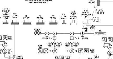
A family of graphic symbols has been developed to represent fluid power components and systems on schematic drawings.
Hydraulic schematic symbol chart. Schematic symbols and circuit design help. General symbol push knob push pull knob single pedal double acting pedal plunger plunger with stroke limitation spring roller lever wrrh roller single solenoid pushpull solenoid direct pilot operated pneumatic hydraulic operated electric motor other control unit not electric motor intermediate position proportional spool coupling internal. 122 purpose 1221 the purpose of this standard is to provide a system of fluid power graphic symbols for industrial and educational purposes. Differentiate between hydraulic and pneumatic fluid power media.
Cylinders single acting cylinder symbols returned by external force returned by spring or extended by spring force. If you experience any problems with the site please contact pete hoffman immediately so corrections can be made. But if you only sometimes dabble in it or need other types of symbols to go with hydraulic or pneumatic symbols you might want to check out radica softwares electrical pneumatic hydraulic and electronic symbols library which offers hundreds of many types of symbols that are easily. Laying each symbol out on the page in the same sequence the components are used in the circuit allows people to understand the complete function of the hydraulic equipment.
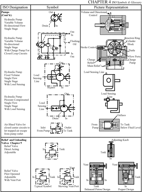
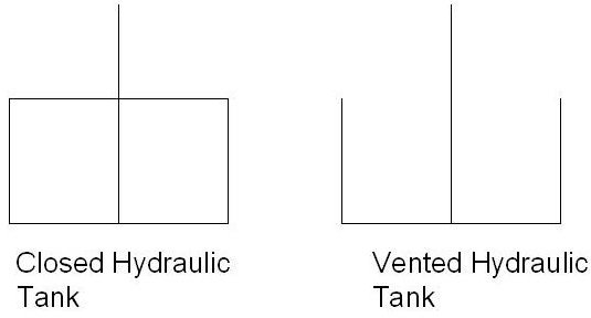
Hydraulic symbols provide a clear representation of the function of each hydraulic component. Circular large circle pump motor small circle measuring devices semi circle rotary actuator square one square pressure control. The institute controls the make up of symbols and makes changes or additions as required. Hydraulic schematic symbols airline hydraulics main page basic symbols lines continuous line flow line dashed line pilot drain envelope long and short dashes around two or more component symbols.
Hydraulic symbols lines line working main line pilot or drain flow direction hydraulic pneumatic lines crossing lines joining lines with fixed restriction line flexible station testing measurement or power take off variable component run arrow through symbol at 450 pressure compensated units arrow parallel to short side of symbol. Pete can be reached on campus via email at phoffmanatswtcedu or by phone at 18003623322 ext 2727. 1222 the purpose of this standard is to simplify page 1 of 24. Hydraulic and pneumatic picture symbols for fluid power schematics define their function in engineering drawings diagrams or plans.
Airline hydraulics schematic symbols chart design hydraulic and pneumatic circuitsdiagrams created date. If you draw pneumatic schematics regularly you probably have sources of standard hydraulic symbols.

What S The Difference Between Hydraulic Circuit Symbols Machine Design

Hydraulic Circuits Apparatus For Testing The Strength Of A Hydraulic Hose Splice Hydraulic Schematic Retract Resistor Check Valve Application Hydraulic Circuit Diagram Wikipedia

Jic Standard Symbols For Electrical Ladder Diagrams Womack Machine Supply Company
Simple Basic Hydraulic Symbols

Academic Textbook Fluid Power Control Systems The Lecture 15 Hours Kielce University Of Technology Faculty Of Mechatronics And Machine Design Pdf Free Download
Glossary Of Iso Hydraulic Schematic Symbols And Their Meanings Bright Hub Engineering

Solenoid Valves Discrete Control System Elements Automation Textbook

How To Read Schematics Vol 1 Electrical Process Audioeverthing

Hydraulic Symbols Valve Actuator
