Isolated Ground System Wiring Diagram

Hunter 27183 Wiring Diagram Diagram Base Website Wiring Diagram
Electrical And Fire Safety Anesthesia Key

Installation Diagrams
An isolated ground if installed correctly can reduce some electrical noise.
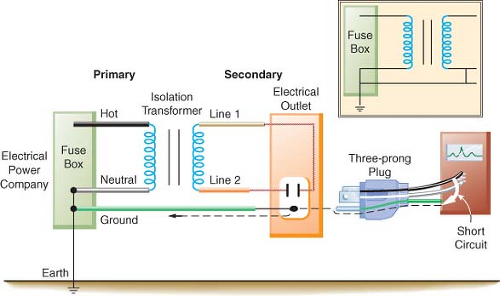
Isolated ground system wiring diagram. Until the 1950s isolated ground domestic mains supplies tended to have no residual current device rcd or earth leakage circuit breaker elcb and too high a ground impedance to blow a fuse if. The british term for isolated ground is it from the french terre isolee. Isolated ground system the isolated ground system ig relies on bringing an equipment grounding conductor egc all the way from the point of ground origin such as a load center electrical panel etc to the point where it terminates onto the load that it is serving without ever contacting another equipment ground metal outlet box metallic conduit system etc. 26052602 isolated ground receptacle wiring diagram alt default.
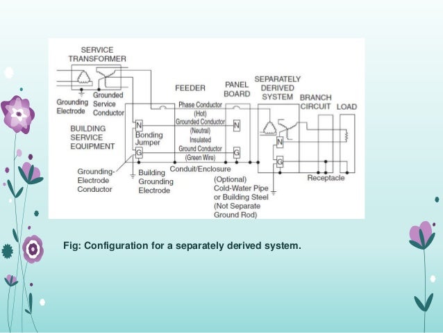
Isolated ground receptacles 51716 3min. A basic diagram of this type of improper wiring can be seen below where a separately driven ground rod is used to reference the insulated equipment grounding bus in a sub panel. The grounding terminal for an igr is insulated from its metal mounting yoke. How to install a ground bar in a sub panel or main load center.
To originate an ig ground wire at the transformer simply carry a separate ig ground conductor from the equipment ground point in the transformer to an isolated ground bar in the secondary panel. However complete power conditioning and protection usually requires additional devices such as a surge protector or an uninterruptible power supply. An isolated ground receptacle igr can reduce electrical noise but if installed incorrectly it can create a dangerous installation. Crazy vato installs isolated ground receptacle robert salazar.
This means you must connect the grounding terminal directly to an effective fault current path by an insulated. This receptacle differs in construction from its self grounding counterpart. Isolated ground receptacle wiring diagram wiring diagram is a simplified gratifying pictorial representation of an electrical circuitit shows the components of the circuit as simplified shapes and the power and signal connections amid the devices. Ig wiring on direct connected circuits as per 25096b isolated grounding circuits where required for the reduction of electrical noise electromagnetic interference on the grounding circuit an equipment enclosure supplied by a branch circuit shall be permitted to be isolated from a raceway containing circuits supplying only that equipment by one or more listed nonmetallic raceway.
In 1984 responding to this and other incidents the authors of the national electrical code provided installation requirements for an isolated equipment grounding conductor.
Ground Earth And Chassis Explained Lednique

500d418 Isolated Ground System Wiring Diagram Wiring Library

Ten Deadly Conditions On Boat Electrical Systems West Marine

Enphase Installations Simplified By Integrated Ground Technology
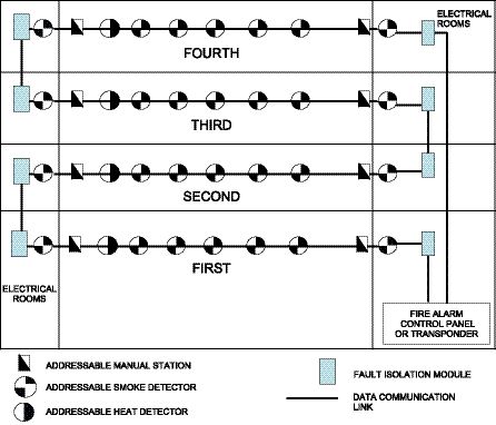
Addressable Fire Alarms Canadian Consulting Engineer

Ground Loop Electricity Wikipedia
Https Www Defender Com Pdf 24v Alt Pdf

How To Eliminate Ground Loops With Signal Isolation Projects

Em 9417 Nec Service Ground Wire Diagram Free Diagram
