Isolation Relay Wiring Diagram
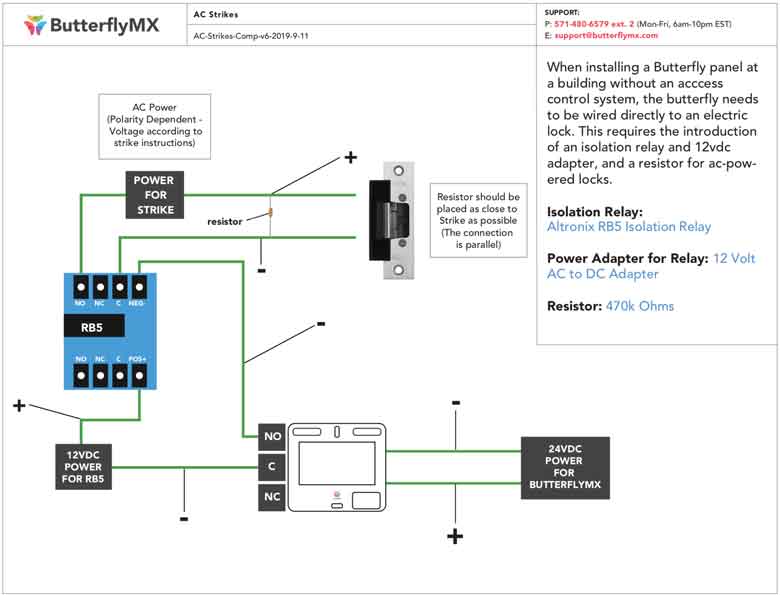
Installer Documentation Butterflymx

Odd Thermostat Fan On Issue Hvac Diy Chatroom Home

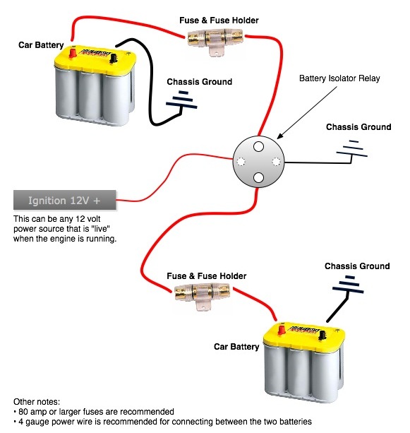
Battery Management Wiring Schematics For Typical Applications
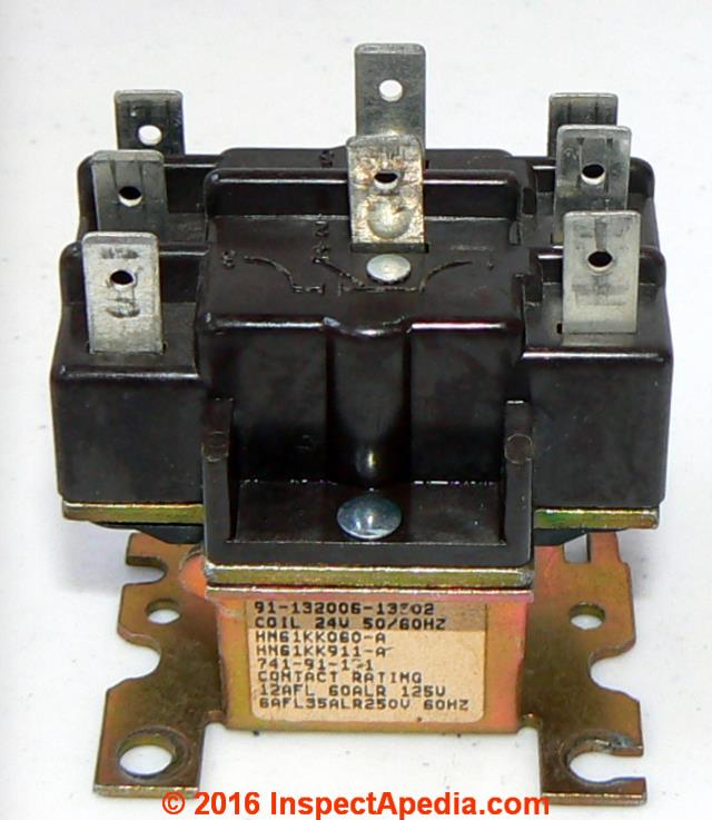
Isolation relay hn61kk066 1 installation instructions 1 warning.
Isolation relay wiring diagram. Power light will always be off. Best bosch relay wiring diagram 5 pole electrical outlet symbol 2018. Dual battery isolator wiring diagram dual battery isolator circuit diagram dual battery isolator switch wiring diagram dual battery isolator wiring diagram every electric structure is made up of various unique pieces. It is controlled by the logic board.
12 volt wiring diagram best 12v relay pin 5 and roc grp org in. Ecobee3 lite with 3 wire hot water zone valves. Energizing this coil closed the relay and places the batteries in parallel. A wiring diagram is a streamlined conventional pictorial representation of an electric circuit.
When using alternative wiring diagram the boiler oper ating controls zc terminal will see the load of the circulators. Each component should be placed and linked to other parts in particular way. The k y z inputs are connected through leds which provide an indication of connectivity. 3 wire heat only thermostat r g w installing your ecobee with a boiler and ac dual transformer system ecobee thermostat installation with an isolation relay.
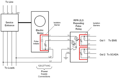
It shows the components of the circuit as simplified shapes as well as the power as well as signal connections between the devices. Assortment of battery isolator wiring schematic. A typical utility customer interface is shown in the figure 1. Smartthermostat with voice control and ecobee4 wiring diagrams.
12 volt relay wiring diagram collections of best relay wiring diagram 5 pin bosch endearing enchanting blurts. The latching isolation relay modules are designed utilizing mercury wetted relays to provide the required equipment isolation. It is controlled by the logic board. Electrical shock can cause personal injury or death.
The relay coil is what causes the contacts to move from open to closed or from closed to open. Before beginning any installation or modification be sure the main electrical disconnect switch is in the off position. 24 vac signal stat light will go on and off with 24 vac signal. Our kit includes separate relays for the high and low beams as well as upgraded gxl wire to make fresh connections to your lights.
Https Customer Resideo Com Resources Techlit Techlitdocuments 60 0000s 60 2171 Pdf
2003 Chevy Pick Up Wiring Diagram Diagram Base Website Wiring
Honeywell L4064b Combination Fan And Limit Control How To Set The

3 Port Protection 4 Isolation Relays Nxt 2 D 4 D Controller
1982 85 6 Firebird Headlight Actuator Relay Spdt Conversion

Ic693mdl930 Manualzz
Https Static Nhtsa Gov Odi Rcl 2016 Rcmn 16v103 0003 Pdf
Line Voltage Vs Low Voltage What S The Difference Ssi News

2001 Impala Fuse Box Wiring Library
