Isolation Transformer Schematic

Isolation Plitron Manufacturing

Autotransformer Vs Isolation Transformer Isolation Transformer
Where And Why Are Isolation Transformers Used Quora
Order before 1200pm sydney time same day 600pm sydney time next day mon fri.

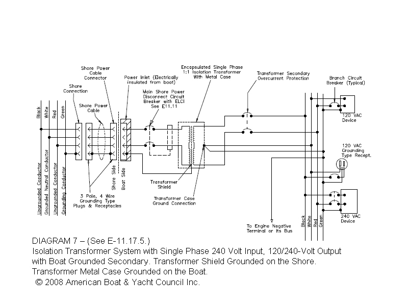
Isolation transformer schematic. On the schematic they are calling t1 a isolation transformer. Icons that stand for the components in the circuit. Electrical isolation is necessary to protect circuits equipment and people from shocks and short circuits as well as to make accurate measurements. Shielded isolation transformers can prevent transfer of common mode noise from primary to secondary when the secondary of isolation transformer is ungrounded.
An isolation transformer is a transformer used to transfer electrical power from a source of alternating current ac power to some equipment or device while isolating the powered device from the power source usually for safety reasons. The in built isolation transformer creates a new live and neutral and the online double conversion technology then ensures a high quality stable output. Transformer with ungrounded secondary. Thank you for any input.
Isolation transformer wiring diagram. A wiring diagram is a kind of schematic which utilizes abstract photographic symbols to reveal all the interconnections of components in a system. Hey guys got a kay 703 c practice amp on the bench. Is this truly a isolation transformer for todays safety standards.
Circuitry diagrams are made up of 2 points. The role of isolation transformers in data center ups systems contents executive summary revision 0 by neil rasmussen white paper 98 introduction2 the role of transformers in ups systems 2 transformer arrangements in practical ups systems 10 transformer based legacy ups designs 21 transformer options within a ups product 24 conclusion25. Step up step down and isolation transformers ac electric circuits pdf version. Transformer isolation july 31 2015 by marie christiano an in depth look at transformer isolation.
The amp hums bad so its going to need new filter caps and a 3 conductor grounding power chord. Shown here is a schematic diagram of a transformer powering a resistive load at the exact moment in time where the primary windings voltage is at its positive peak. Common mode currents are essentially zero sequence currents flowing in the primary circuit towards the isolation transformer. Isolation transformers provide galvanic isolation and are used to protect against electric shock to suppress electrical noise in sensitive devices or to.

Connector Kits And Isolation Transformers Hughey And Phillips
Rcd Elci Gfi Between Abyc And Iso Codes Page 3 Boat Design Net
Diy Isolation Transformer
Isolation Transformer

Epanorama Net View Topic Isolation Transformer

Isolation Transformer Potential To Earth Ground Electronics Forums

Reducing The Size And Complexity Of An Isolated Synchronous Gate
Ion Source Prototype Schematic View 1 Isolation Transformer 2

What Is An Isolation Transformer R Baker Electrical Ltd
