Ladder Diagram Of Logic Gates
Logic Gates In Plc Ladder Logic Instrumentation Tools
Xnor Plc Ladder
The Decision Makers And Or And Not Plcdev
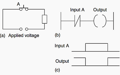
The ladder diagram starts with a normally open set of contacts labeled input a to represent switch a and in.
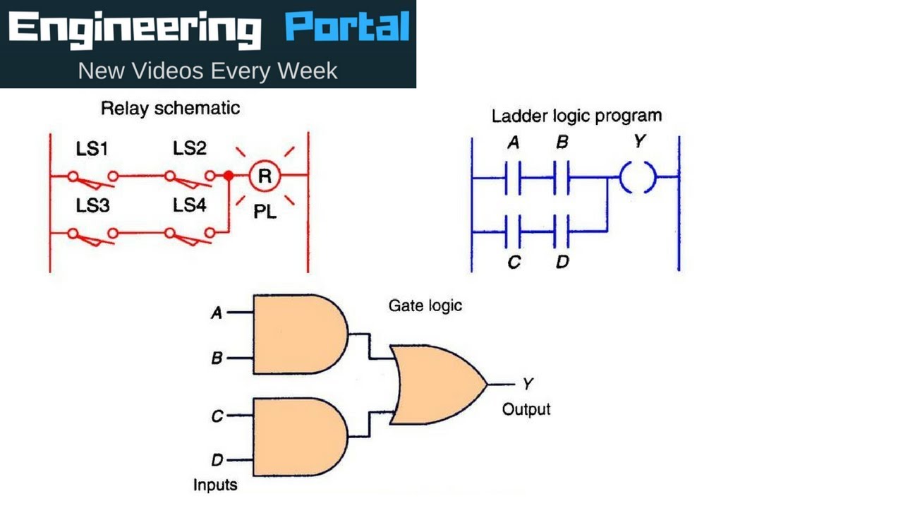
Ladder diagram of logic gates. Each device in the relay rack would be represented by a symbol on the ladder diagram with connections between those devices shown. Show the equivalent logic gates using plc ladder diagrams. Logic gates using plc programming explained with ladder diagram june 15 2020 june 6 2018 by dipali chaudhari as we all know logic gate is a building block for the digital circuit. In this video we are going to learn how to make digital logic gate and or nor xor in the ladder programming.
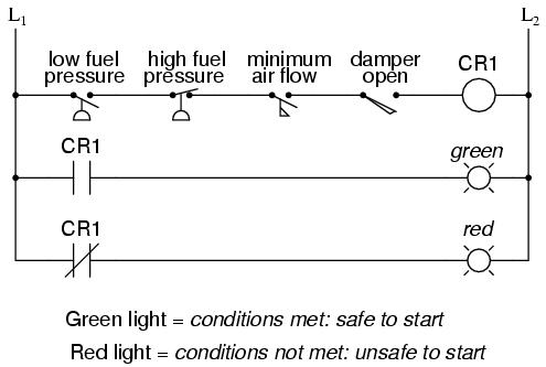
Ladder logic was originally a written method to document the design and construction of relay racks as used in manufacturing and process control. Figure 2a shows an and gate system on a ladder diagram. An example of an and gate is an interlock control system for a machine tool so that it can only be operated when the safety guard is in position and the power switched on. Ladder diagram basics 3c 3 wire control duration.
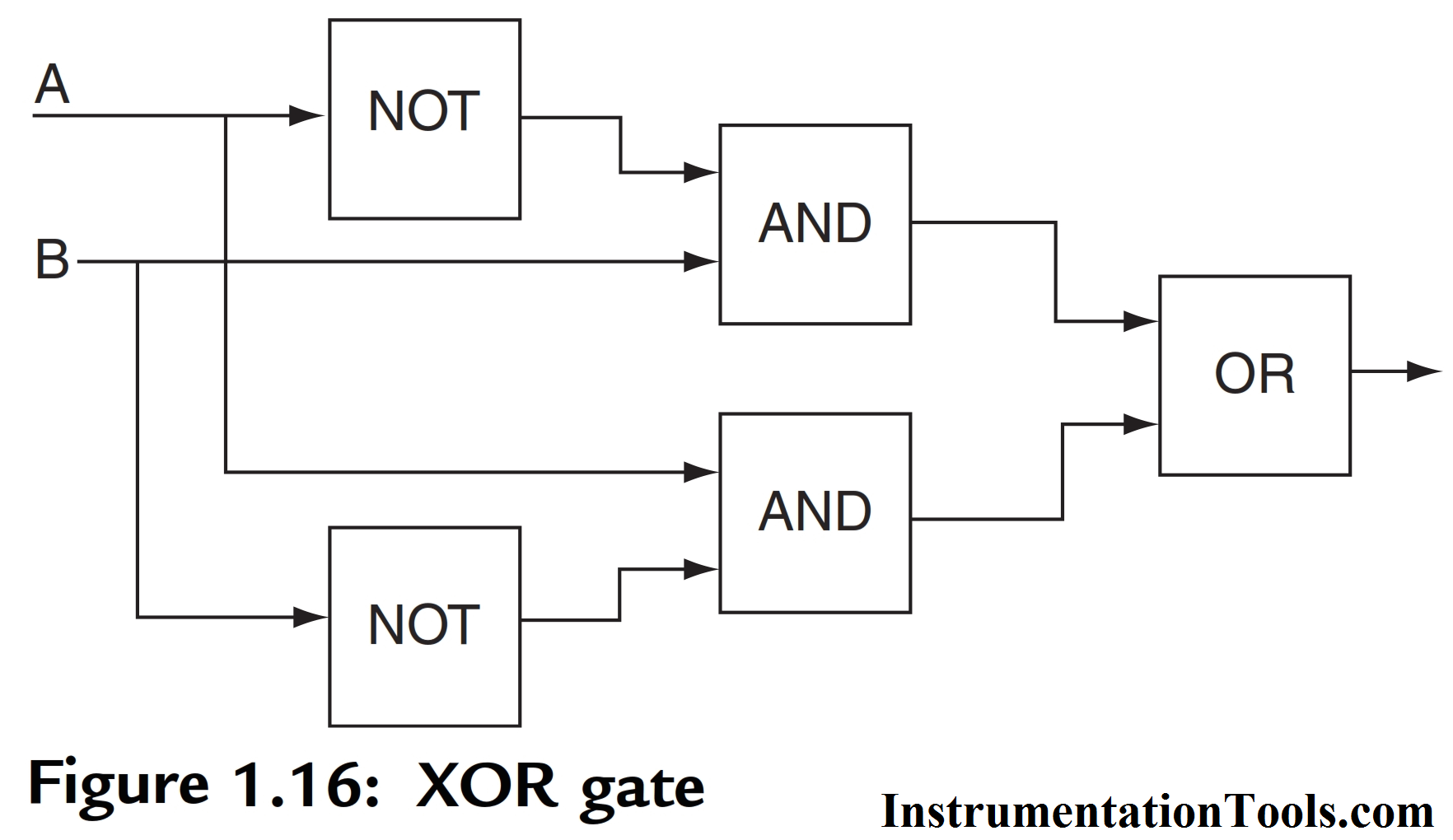
Computer logic gates in minecraft. In the previous post logical gates in ladder logic for plc we had an overview of what is ladder logic programming and we have also implemented three basic logical gates in ladder logic formtoday we are gonna have a look at some complex logical gates in ladder logic for plc. I am leaving the xnor gate truth table and the xnor gate plc ladder logic diagram as an assignment for you. Logic gates vs ladder logic circuits engineering portal.
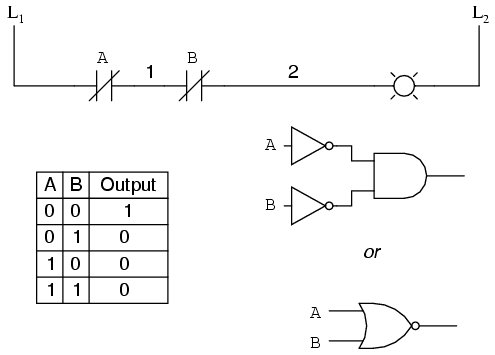
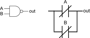
Xnor gate plc ladder logic diagram. Figure 1 a and circuit b and logic gate. Let me know in the comment the output of the xnor gate. Logic gates in plc ladder logic we can construct simply logic functions for our hypothetical lamp circuit using multiple contacts and document these circuits quite easily and understandably with additional rungs to our original ladder if we use standard binary notation for the status of the switches and lamp 0.
Pete vree 37991 views. These videos are only to understand how automation work for education purpose. So i hope till now you guys have basic knowledge of ladder logic and can implement complex logical gates in it.
Lessons In Electric Circuits Volume Iv Digital Chapter 6

Plc Program For Star Delta Motor Starter Ladder Logic

Ladder Logic Examples And Plc Programming Examples

Plc Lab Exercise Logic Gates Plc Ladder Logic Diagram Examples
Ebook Automating Manufacturing Systems With Plcs

Logic To Ladder Diagram Logic Gate Programmable Logic Controller
Logic Gates Vs Ladder Logic Circuits Youtube
Ladder Logic Tutorial With Ladder Logic Symbols Diagrams
Plc Ladder Logic Functions For Electrical Engineers
