Ladder Schematic Symbols
Https Abe Ufl Edu Faculty Tburks Presentations Abe5152 Electrical 20symbols 20and 20line 20diagrams Pdf

Jic Nfpa Symbols

Jic Standard Symbols For Electrical Ladder Diagrams Womack
Ladder diagrams are used to depict electronic control circuits in a simple form.

Ladder schematic symbols. As an introduction to ladder diagrams consider the simple wiring diagram for an electrical circuit in figure 1athe diagram shows the circuit for switching on or off an electric motor. Introduction to plc ladder diagrams. They are standard jic joint industrial council symbols as approved and adopted by the nmtba national machine tool builders association. There are typically two distinct parts of a ladder drawing.
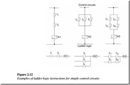
The last instruction required to complete a ladder logic program is the end instruction. The ladder logic symbols that are used in ladder logic programming have been derived from traditional relay logic control circuits. The most common ladder logic program instructions and the symbols used are shown in the figure 211. Ladder logic was designed to have the same look and feel as electrical ladder diagrams but with ladder logic the physical contacts and coils are replaced with memory bits.
For this program the relay logics ladder diagram is duplicated with ladder logic. The ladder diagram graphical programming language is standardized by the plcopen organization and thereby the symbols used in ladder diagramssince ladder logic is a graphical programming language the plc programs written in ladder logic are a combination of ladder logic symbols. Electrical symbols electronic circuit symbols of schematic diagram resistor capacitor inductor relay switch wire ground diode led transistor power. If you have a basic knowledge of electric circuits then getting started in ladder logic programming should be a breeze.
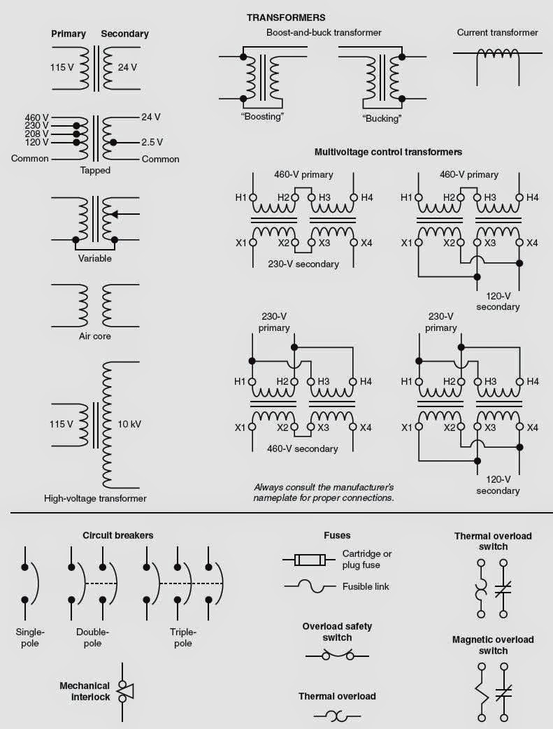
The power component and the control component. When the plc cpu cycle runs through the program it executes all the instructions up to the first end instruction. Special symbols are used to show the different components depicted on the diagram. A wiring diagram is an electrical print that shows connections of all components in a piece of equipmenta schematic diagram is a type of drawing that illustrates the electrical connections and functions of specific circuit arrangements with graphic symbolsa ladder diagram is a diagram that explains the logic of the electrical circuit or system using standard nema or iec symbols.
These graphic symbols are the ones used most often on ladder diagrams for fluid power electrical control circuits. These schematic diagrams resemble a ladder with rails and rungs.
Electrical Wiring Diagrams For Air Conditioning Systems Part One

Ladder Logic Symbols All Plc Diagram Symbols
Http Ee Sharif Edu Industrialcontrol Ladder Logic Tutorial Pdf
Ebook Automating Manufacturing Systems With Plcs

Tutorial Control Fundamentals Plcs Are Logical Choice Isa
Devices Symbols And Circuits Reading And Understanding Ladder

Figure 1 From Rtl Logic Realization Using Ladder Diagram For

Ac Motor Control Circuits Pdf Free Download

Schematic Diagrams For Hvac Systems Modernize
