Light Sensor Switch Circuit Diagram
Https Encrypted Tbn0 Gstatic Com Images Q Tbn 3aand9gcqying8l7dt Sx6fquwnldldmes43znsj7ii3xuylykvurjw1jih1hjd2pln4aycr8 Usqp Cau

Sensors Robotics Tutorials Beginners

Zz 4015 Light Sensor Alarm Circuits Download Diagram
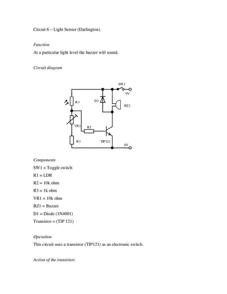
It is the dual transistors type that connecting together in the darlington form.

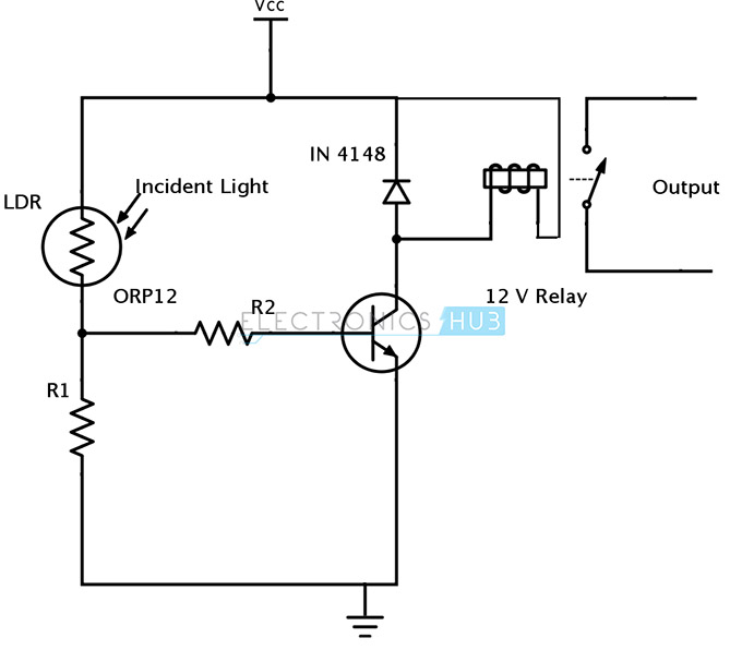
Light sensor switch circuit diagram. Then automatic light switched on. Light sensor circuit working operation. The circuit shown in figure 2 is using a relay at its output and when light falls on the ldr it will activate the relay. A wiring diagram is a simplified conventional pictorial depiction of an electrical circuit.
A few light sensor circuit based projects can be listed as a solar highway lighting system with auto turn off in daytime security alarm system by photo electric sensor sunset to sunrise lighting switch arduino managed high sensitive ldr based power saver for street light control system etc. To make light sensor or simple touch switch circuit. This handy little circuit can tell the difference between darkness and light making it very useful for switching on and off signs porch lights or other things when it gets dark or light. Hi i have a 4 kw solar pv system and i am looking to buybuild a darklight sensor switch to use as a switch in line into the domestic supply to turn on and off an electric oil filled radiator rated 1 or 2 kw when the solar panels are generating enough power to run the heater.
In this experiment we use the phototransistors in the circuit diagram. Here is the schematic for the circuit. The figures below are showing two different light sensor circuits. When any person animal or any object comes in the range of the sensor.
Automatic wash room light controller using pir motion sensor and motion sensor alarm circuit using pir sensor. A 230v ac supply is provided to the load in this case the load is represented with a lamp. This ldr circuit diagram shows how you can make a light detector. It reveals the elements of the circuit as streamlined shapes and also the power and also signal connections between the tools.
Using this circuit an electrical device or an appliance like a light bulb or a fan for example can be controlled based on the intensity of the light near the circuit. Variety of motion sensor light wiring diagram. In this circuit pir passive infrared sensor is used which is used as motion detector. An ldr or light dependent resistor is a resistor where the resistance decreases with the strength of the light.
See digital electronics projects using flip flop switch circuit. The circuit shown in figure 1 is a very simple light sensor circuit that will activate an led when the ldr in the circuit receives light.

Touch Sensitive Light Switch Circuit Diagram Youtube

Zn 5828 Circuit Diagram Using Ldr Schematic Wiring

Xm 1317 Pir Motion Sensor Switch Circuit Schematic Schematic Wiring

Light Sensor Including Photocell And Ldr Sensor
Sensing Part One Stem
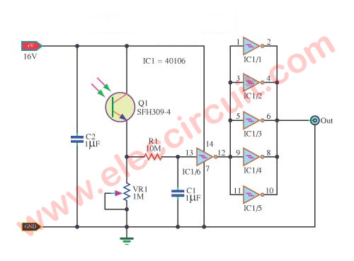
Simple Light Controller Circuit Using Cd40106 Eleccircuit
Light Sensor Using Ldr Photodiode And Phototransistor

Light Sensitive Circuits Nuts Volts Magazine

230v Automatic Night Lamp Electronic Schematic Diagram
