Light Switch Receptacle Wiring Diagram

Outlet Light Switch Home Wiring Diagram Diagram Base Website
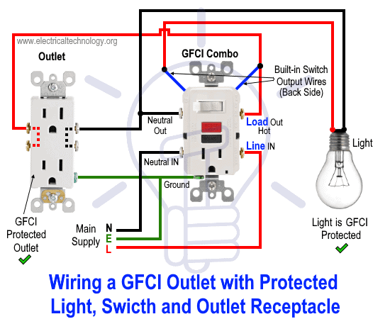
How To Wire Gfci Combo Switch Outlet Gfci Switch Outlet Wiring

E85e2 Ceiling Fan Wiring Diagram Power Into Light Single Dimmer
The light switch is wired so it controls the hot side of the power then the power source continues up to the light fixture.

Light switch receptacle wiring diagram. Scenario 2 a typical example of this situation is if you had the same scenario as above but with a 3 wire circuit such as in a kitchen split receptacle and wanting to add some under counter lighting for example. The source is at the outlet and a switch loop is added to a new switch. It means all the connected loads to the load terminals of gfci are protected. In this video i will show you how to wire a switched receptacle.
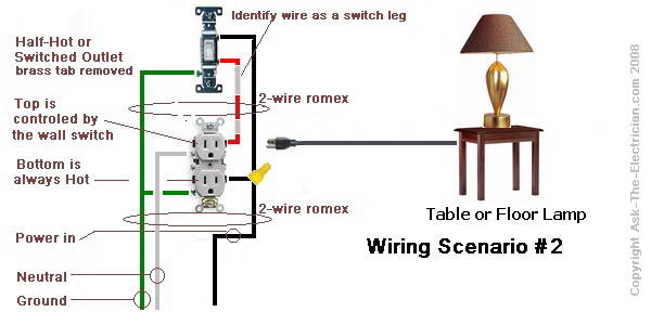
In the diagram below right a 2 wire nm cable that connects the light fixture to the switch carries 2 line wires one line and one switched line. The hot source wire is removed from the receptacle and spliced to the red wire running to the switch. Multiple receptacle outlets can be connected with lighting outlets as depicted in the above light switch wiring diagram. A switch loop single pole switches light dimmer and a few choices for wiring a outlet switch combo device.
The above wiring circuit was made using only a two conductor cable with ground. This page contains wiring diagrams for household light switches and includes. Wiring a light switch diagram 1. In this gfci outlet wiring and installation diagram the combo switch outlet spst single way switch and ordinary outlet is connected to the load side of gfci.
Wiring receptacles and light switches. Duplex receptacle outlets are made for feed through of the power from one receptacle to the next. Also included are wiring arrangements for multiple light fixtures controlled by one switch two switches on one box and a split receptacle controlled by two switches. Wiring a gfci outlet with combo switch outlet receptacle light switch.
Outlets are split wired so that the top half of the receptacle is live all of the time and the bottom of the receptacle is controlled by the wall switch. I will be using very minimal tools that you might find around your home to get this job done. The black wire from the switch connects to the hot on the receptacle. Fishing in a wire from the receptacle to the light fixture is fairly easy so this is how you would wire the switchreceptacle combo device in this situation.
With alternate light switch wiring an nm cable supplies line voltage from the electrical panel to a light fixture outlet box. How to wire a switch receptacle. This wiring diagram illustrates adding wiring for a light switch to control an existing wall outlet. Another nm cable connects from the light fixture box to the switch box.
Shannon the power source is provided to the outlets and up to the light switch.
House Electrical Wiring Connection Diagrams
How To Wire A Switched Outlet With Wiring Diagrams

Wiring Diagram For A Light Switch

Wiring Diagram On Gfci Outlet Wiring Diagram Also A Light Switch

How To Wire A Switch Light Then Switch At End Of Circuit

How To Wire A 3 Way Light Switch Family Handyman

Light Switch Receptacle Wiring Diagram Diagram Base Website Wiring

Wiring Diagram For Light Switch 101warren

Smart Light Switch Wiring Diagrams Mr Electrician
