Logic Diagram For Bcd To 7 Segment Decoder
How To Build A 4511 Bcd To 7 Segment Decoder Circuit
Bcd To Seven Segment Decoder Display Theory Circuit And Working

Bcd To 7 Segment Display Circuit
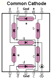
Seven segment displays are widely used in digital clocks electronic meters and other electronic devices that display numerical information.
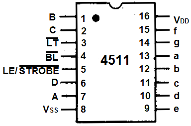
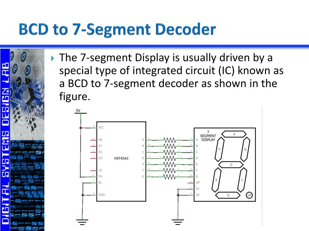
Logic diagram for bcd to 7 segment decoder. 7 segment led light emitting diode or lcd liquid crystal display type displays provide a very convenient way of displaying information or digital data in the form of numbers. The cd74hct4511e is a cmos logic high speed bcd to 7 segment latchdecoderdriver with four inputs and is used to use these 4 inputs bcd nibble to control the display of a 7 segment display. A digital decoder ic is a device which converts one digital format into another and one of the most commonly used devices for doing this is called the binary coded decimal bcd to 7 segment display decoder. Schematic of bcd to 7 segment display decoder.
A seven segment display is an electronic display device for displaying decimal numerals. Bcd to 7 segment display decoder part 1 tech gurukul by dinesh arya check out my amazon store httpswwwamazoninshoptechgurukuldescription a bcd to. Like the bcd decimal decoder the bcd to seven segment decoder is a complicated logic network. Bcd to 7 segment display decoder part 3 tech gurukul by dinesh arya description a bcd to seven segment decoder is a combinational logic circuit that accepts a.
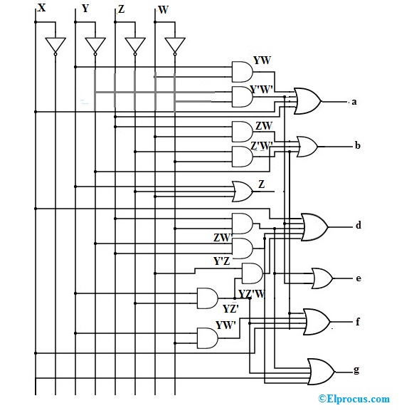
The decoder is an essential component in bcd to seven segment decoder. Bcd to 7 segment display. Bcd to 7 segment display integrated circuit all these 7 logic gates diagrams can all be integrated into one single integrated circuit. A decoder is nothing but a combinational logic circuit mainly used for converting a bcd to an equivalent decimal number.
Bcd to seven segment display decoder theory. The schematic shows a bcd to 7 segment display for one of the digits of a digital clock. A combinational logic circuit is a system of logic gates consisting of only outputs and inputs. 7 segment display decoder circuit.
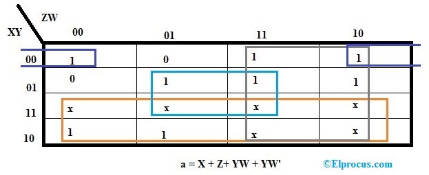
The circuits accept 4 bit binary coded decimal bcd and depending on the state of the auxiliary inputs decodes this data to drive a 7 segment display indicator. A combinational logic circuit can be built with logic gates which. The relative positive logic output levels as well as conditions required at the auxiliary inputs are shown in the truth tables. We have derived an expression for each output now we need to make its schematic using logic gates as shown in the figure given below.
It can be a bcd to seven segment decoder.
Bcd To Seven Segment Decoder Display Theory Circuit And Working

Bcd To Seven Segment Decoder Ic Description Dictionary Of

Bcd To Seven Segment Decoder Electrical4u

7 Segment Display And Driving A 7 Segment Display
Ppt Digital Outputs 7 Segment Display Powerpoint Presentation
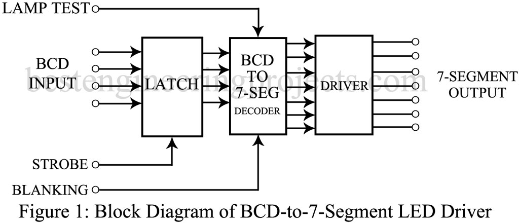
Bcd To 7 Segment Display Driver Sn74143 Engineering Projects
Encoders And Decoders

Bcd To Seven Segment Decoder
Bcd To 7 Segment Led Display Decoder Circuit Diagram And Working
