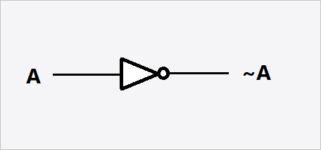
Logic Gates Logic Diagram Symbols
That is it performs a logical operation on one or more logical inputs and produces a single logical output.

Logic gates logic diagram symbols. Depending on the context the term may refer to an ideal logic gate one that has for instance zero rise time and unlimited fan out or it may refer to a non ideal physical device see ideal and real op amps. The following two figures which use a common facility startstop pump circuit as an example clearly demonstrate the reasons for learning to read logic diagrams. The logic symbols called gates depict the operationstartstop circuits of components and systems. The logic gate software has all the logic symbols you need to design any kind of logic model.
A logic gate is an elementary building block of an electrical circuit. Electrical symbols logic gate diagram. The logic symbols called gates depict the operationstartstop circuits of components and systems. Most logic gates have two inputs and one output.
In electronics a logic gate is an idealized or physical device implementing a boolean function. A logic gate is an idealized or physical electronic device implementing a boolean function a logical operation performed on one or more binary inputs that produces a single binary output. Figure 1 presents a schematic for a large pump and. The traditional symbols have distinctive shapes making them easy to recognise they are widely used in industry and education.
There are two series of symbols for logic gates. The iec international electrotechnical commission symbols are rectangles with a symbol inside to show the gate function. Some circuits may have only a few logic gates while others such as microprocessors may have millions of them. The following two figures which use a common facility startstop pump circuit as an example clearly demonstrate the reasons for learning to read logic diagrams.