Loop Powered 4 20ma Circuit Diagram
Wire Diagram

2 Wire Loop Powered Transmitter Current Loops Understanding

Ground Loops In 4 20 Ma Signals Youtube
This is fed to close loop control system of ic3a inverting pin.
Loop powered 4 20ma circuit diagram. Troubleshooting a 4 20ma current loop s bharadwaj reddy may 13 2016 april 9 2019 the basic layout of every 4 20ma loop consists of a power supply a transmitter and passive loop devices. Current loops are ideal for data transmission because of their inherent insensitivity to electrical noise. Frequently a transmitter is labeled as power. A basic guide on how to hook up a 4 20ma loop powered pressure transmitter.
Loop powered devices are often much lower cost than other process control devices with built in high power electronics. We will use the lower of the voltages in the calculation. If the devices in the loop require more voltage to operate than the power supply delivers. What is the analogue input output.
This is provided by the power supply with the voltage of the supply labeled as vtot. In a 4 20ma current loop all the signalling current flows through all devices. The 4 20ma current loop is a very robust and popular sensor signalling standard. In this video you will get the following discussion.
This is simply because the expensive components that could be included in these devices such as power supplies mechanical relays or advanced digital or analog signal output components are omitted in order to limit the amount of power necessary to operate the device. There can be only one transmitter output in any. Current then flows through the loop passing through each load. Analog signals are the most common term in industrial automation.
X to y volts. This is the device used to transmit data from a sensor over the two wire current loop. Schematic diagram for the voltage to current converter hi all expert i need a circuit diagram that convert 0ohm 100m ohm to 4 20ma or 1 5v with the zero and span adjust. A current loop requires voltage to drive the current.
Troubleshooting a 420ma loop page 3 of 4 power supply malfunctioning electronics etc arent part of troubleshooting a 420ma loop unless the loop is being powered by a supply that is part of the indicator and one can continue by repairing the indicator to resolve these issues. Ohms law states that voltage equals current multiplied by resistance so multiply the resistance by 002 and the resulting figure is the voltage we desire. The voltage drop at each load can be calculated from ohms. Problems with transmitters usually occur because of wiring.
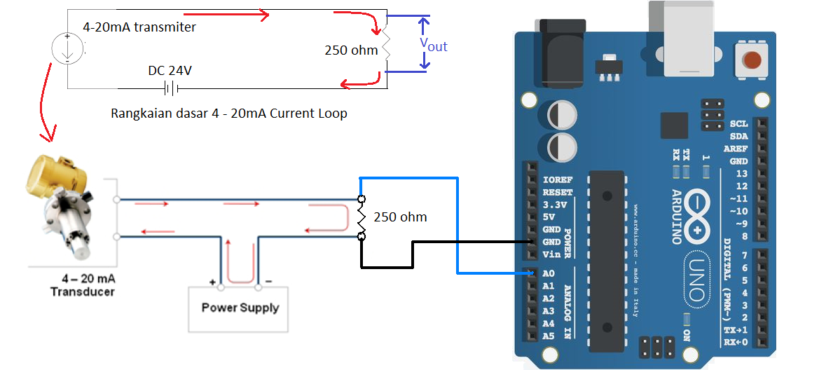
Arduino 4 20mamp Current Loop Measurement Circuits4you Com

Az 4 20ma F Two Wires Loop Powered Distributor Module Signal

2 Wire 4 20ma Sensor Transmitters Designing Input Isolated 2 Wire

High Accuracy 4 20 Ma Current Loop Transmitter Eeweb Community

I Q Instruments Using 4 20ma Current Loops

4 20 Ma 2 Wire Current Loop Sensor
1
Https Encrypted Tbn0 Gstatic Com Images Q Tbn 3aand9gcq2wue1zmez158dbrcnd3xvgi3sz1ez5x2pmjtnor8v5pvnhbte Usqp Cau

China Two Wire Loop Powered Ac Signal To 4 20ma Signal Converters
