Lutron Dimmer Ballast Wiring Diagram

H3dt550gu210 Formerly Eco T550 120 2 Eco T550 277 2 Lutron Hi

Wrg 6273 Graphix Lutron Wiring Diagram
Https Images Homedepot Static Com Catalog Pdfimages 06 06b382f4 E4c7 441d 9e9d E9c620dc1f3e Pdf
December 25 2018 by larry a.
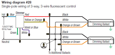
Lutron dimmer ballast wiring diagram. All lutron ballasts are rapid start type which provide supplemental heat to the filaments. Each feature is designed around what is most important to you how well your building is working. Using instant start sockets with a lutron ballast. 8 fluorescent dimming systems technical guide socket wiring socket wiring for t8 and t12 linear for ballasts that control more than one lamp sockets wired to the yellow or blue with white stripe leads of the ballast must be wired in parallelnot in series.
It is therefore important that these two pins are not shorted together in the socket. Ecosystem compact fluorescent ballasts digital dimming ballasts 369339h 6 030618 ecosystem bus wiring diagrams ecosystem digital link overview the ecosystem digital link wiring e1 and e2 connects the digital ballasts and drivers together to form a lighting control system. Easily monitor control and optimize a lutron control system from any tablet pc or smartphone. Rapid start sockets which keep these pin connections separate must be used with lutron ballasts.
Retrofit and small space applications can benefit from the ease of installation offered by lutron tu wire dimming ballasts. Lutrons new facility management tool empowers you to manage your building from anywhere. Tu wire ballasts offer 100 to 5 dimming for linear and compact fluorescent lamps. By providing industry leading performance with a full range of 100 to less than 1 fluorescent dimming hi lume 3d ballasts.
Lutrons ballast options deliver the right solution and performance for virtually any lamp or fixture. Socket wiring for t8 and t12 u bent correct sockets wired in parallel typically yellow. It shows the elements of the circuit as simplified shapes and also the power and also signal connections in between the devices. 010 v is quickly becoming one of the more popular dimming technologies with wired occupancy sensors for v.
Variety of 0 10v dimming ballast wiring diagram. Lutron 0 10v dimmer wiring diagram lutron diva dvstv v dimmer for fluorescent and led the lutron diva dvstv is a v dimmer that easily lutron dvstv v installation instructions. Each ecosystem digital link supports up to 64 digital.

Sr 8999 Lutron Fan Light Dimmer Switch Wiring Diagram Wiring Diagram
Http Www Lutron Com Technicaldocumentlibrary 0301682 Pdf

Scl Iv 153ph Wiring Diagram Lutron Dimmer Switch Diagram Base

Lutron E3t521c1201 Eco 10 Rapid Start Electronic Flourescent

Lutron Maestro Dimmer 3 Way Wiring Diagram Diagram Base Website

Kr 4852 Lutron Pico Wiring Diagrams Free Diagram
691fa Dimmable Led Wiring Diagram Wiring Resources

H3dt832cu110 Lutron Hi Lume Dimming Ballast
Https Www Legrand Us Media Brands Passandseymour Resources Installation Instructions Lighting Controls Dimmers Titan0 10v Install Ashx
