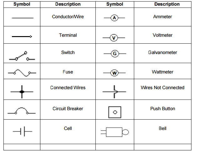
Connecting Wire Schematic Symbol
How To Draw Electrical Diagrams And Wiring Diagrams
Schematic Symbols Learn Parallax Com
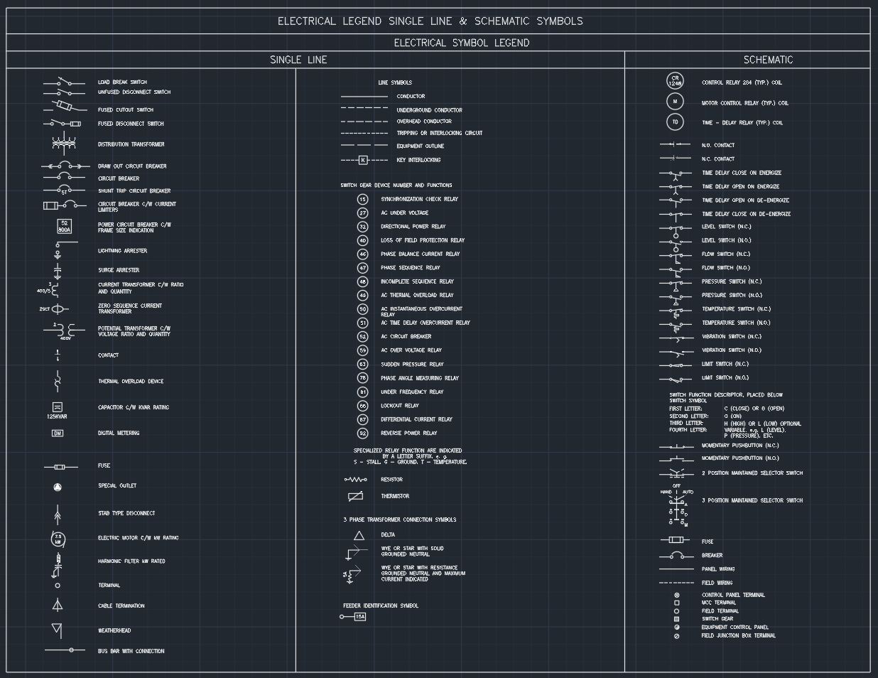
Electrical Legend Single Line Schematic Symbols Cad Block
For each wire connection there is a terminal or connection value attribute term and a wire cutting attribute xterm with the option of a terminal or connection description attribute xtermdesc.

Connecting wire schematic symbol. Electrical symbols electronic circuit symbols of schematic diagram resistor capacitor inductor relay switch wire ground diode led transistor power. The power lines wires cables conductors. By miles nicholson the insertion point of a wire connection point is the location autocad electrical uses to connect the wire. We call the middle pin the wiper.
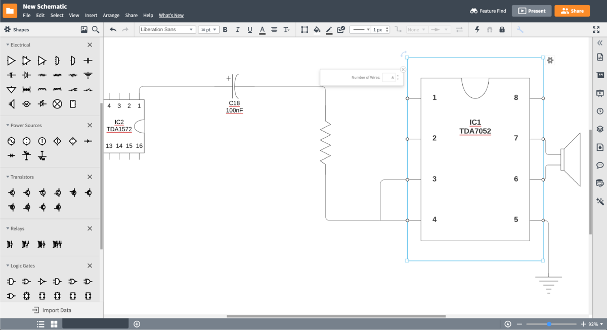
Every symbol on a schematic is given a name and number. And then create the symbol and place the pins for the library base on the datasheet. They are also electrically conductive electrolyte and ionized gases. Are materials that conduct electricity easily such as certain metals.
Document new schematic lib this opens the new schematiclib symbol editor. I have a device that requires 10awg wire and another device that requires 4awg wire. Get the datasheet for example using the ne555dr the datasheet you can refer lcsc. I was wondering if i can include the wire and size on the schematic block.
It has three pins and the schematic symbol looks like this. For example as carbon. Wires in schematic symbol. Start a new schematic lib as shown below or by doing.
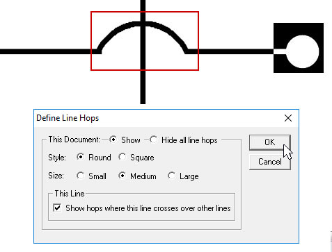
It is connected somewhere on the strip between the two ends. However some people still use the. Older electrical schematics showed connecting wires crossing while non connecting wires jumped over each other with little half circle marks. Electrical connectors consist of plugs male ended and jacks female ended.
Between the two side pins of the potentiometer there is a strip of resistive material. Symbols of lines wires cables and electrical conductors. Newer electrical schematics show connecting wires joining with a dot while non connecting wires cross with no dot. This material creates resistance.
Symbol names will typically be a combination of a letter and a number with the letter identifying the type of part and the number being the unique variation of that symbol.

Kh 4178 Connect Wire Schematic Symbols Free Diagram

Top 10 Tips For Professional Schematic Design Eagle Blog
Understanding Schematics Technical Articles
Lesson 3 T L E Learning Module
Circuit Diagram Maker Lucidchart

How To Construct Wiring Diagrams Industrial Controls

Top 10 Tips For Professional Schematic Design Eagle Blog
How To Read And Understand An Electrical Schematic
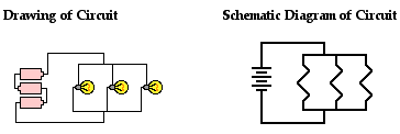
Physics Tutorial Circuit Symbols And Circuit Diagrams
