Dj Audio Mixer Schematic Diagram
Audio Mixer Circuit Audio Circuits Next Gr

3 Channel Audio Mixer Circuit Technologie Informatique

My 3948 Simple 3 Channels Mini Mixer Circuit Diagram Free Diagram
This article discusses about the design of a simple audio mixer circuit.
Dj audio mixer schematic diagram. This simple passive diy stereo audio mixer demonstrates resistors in use. An audio mixer also called a mixing console is an electronic device for combining and modifying audio signalsthe modified audio signals are summed to produce some combined output signals. Block diagram of the audio mixer with bass. Audio schematics mixer circuits.
This is a universal 4 channel dj audio mixer project that may be customized and upgraded to 5 channel or even 10 channel level as desired by the user. 2 line output combiner convert consumer equipment stereo signal to mono or combine audio signal from two different equipments to1 input. The mic inputs are suitable for low impedance 200 1000r dynamic microphones. An op amp based summing amplifier is used here to mix two sounds.
5 stage dj mixer five stages are employed within the layout. The tl062 chip contains two tl061 op amps into the same 8 pin case and is wired as two virtual earth mixer amplifiers having a voltage gain of about 4 to compensate for losses introduced in the passive pan pot circuitry. The input levels can be set by potentiometers p1 or p3. The power supply and audio power amplifier circuits are shown in figs 3 and 4 respectively.
Audio mixers can be analog or digital type. Digital mixing consoles use digital signal processing concepts and analog mixers are usually based on op amps electronic circuits. Mono headphone amplifier stage. Making an audio mixer.
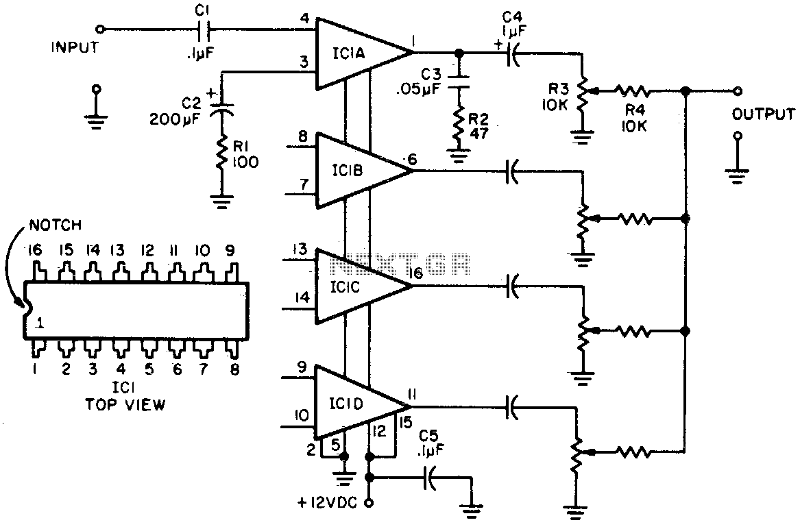
Diagram 10 shows the 3 channel sound mixer circuit using three norton opamps. The audio mixing is demonstrated with the help of mixing a high frequency musical sound with a low frequency bass beat where the musical sound is generated by a musical ic and the bass beat played at a mobile phone and is captured and amplified through a. 6 input mixer mitedu the mixer circuit below has 3 line inputs and 3 mic inputs. Furthermore each input level can be trimmed with the help of trimmers pots p4 to p6 to adapt each input to the source.
The schematic of this circuit is drawn as a stereo unit to better show the input main fader and pan pot connections. Stereo vu circuit stage and general purpose preamplifier stage.

Audio Project Kynix Semiconductor

Od 9913 Two Channel Audio Mixer Circuit Design Electronic Project

Dj Wiring Diagram For Audio Keju Gain Seblock De
Audio Mixer With Multiple Controls Full Circuit Diagram Available

China Ca18 Professional Power Amplifier Dj Power Amplifier Ca20

Beginner S Guide To Pa Systems Part 1 Basics Digital Dj Tips

Server Side Audio File Beat Mixing Us 2009 259 326 A1 Patentswarm
4 Channel Portable Audio Mixer Circuit Diagram

Yz 2277 Passive Audio Mixer Circuit Wiring Diagram
