Fan Limit Switch Wiring Diagram

Fan Limit Switch Help Hvac Diy Chatroom Home Improvement Forum

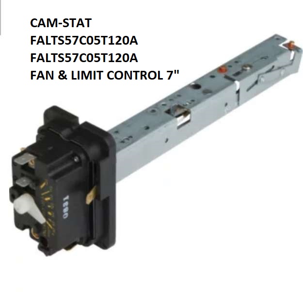
Igus Slider Switch Kit

Unique Wiring Diagram For Underfloor Heating Thermostat Diagrams
Diy tinker 430552 views.

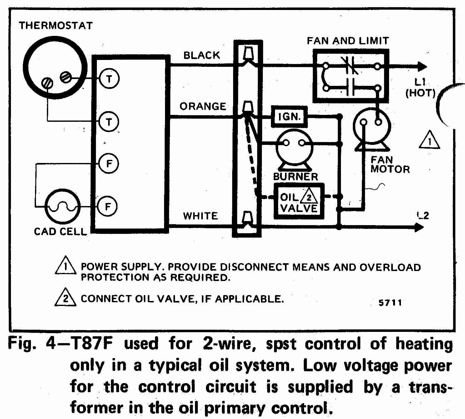
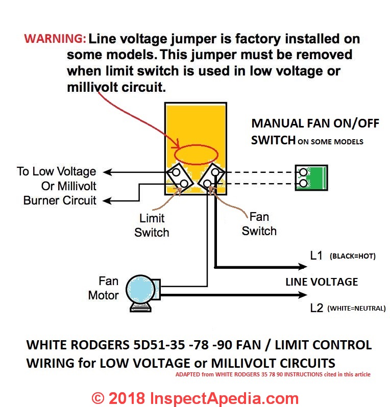
Fan limit switch wiring diagram. This article describes in detail the purpose operation setting installation wiring and testing of furnace combination controls also commonly called the fan limit switch on warm air heating systems. Make l1 hot on 120v installation caution. Line voltage jumper is factory installed on some models. Advice for installing and wiring the furnace combination control fan limit switch on heating systems guide to installing wiring fan limit switches on warm air.
Furnace comes on but blowerfan stays off hvac fan limit control switch replacement ac duration. I am replacing my fan limit switch on my furnace but need help with the simple wiring. I looked on this page and found the following diagram. The explanation is for a honeywell fan limit control but it seems similar enough to the white rodgers device i an using.
I have 3 wires going to it but none match the wiring diagrams of the directionsthe replacement is a newer version of the fan limit switch and i cannot tell if my jumper was removed before. Variety of honeywell limit switch wiring diagram. This jumper must be removed when limit switch. The limit is a high temperature safety limit i guess.
A wiring diagram is a streamlined conventional photographic depiction of an electric circuit. Limit switch fan switch fan motor optional remote manual switch for summer fan to low voltage or millivolt burner circuit diagram using limit in low voltage or millivolt circuit l1 line l2 note. Furnace blower fan limit safety switch installation troubleshooting. Honeywell fan limit switch wiring diagram thanks for visiting my website this blog post will discuss concerning honeywell fan limit switch wiring diagram.
Ok i read a little on the fanlimit control concept. A wiring diagram is a simplified traditional pictorial representation of an electric circuit. Collection of honeywell fan limit switch wiring diagram. Unfortunately i find the explanation to be vague.
It reveals the components of the circuit as streamlined shapes and the power and also signal links in between the devices.

32dbb50 Fan Limit Switch Wiring Diagram Wiring Library
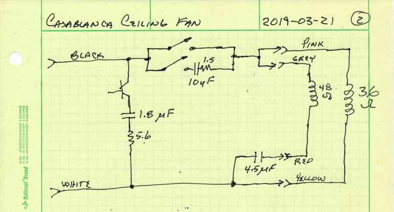
The Casablanca Ceiling Fan Teardown Electronic Design
0d71 Furnace Blower Wiring Diagram Thermostat Wiring Library
How To Install Wire The Fan Limit Controls On Furnaces

Om 4947 Furnace Blower Motor Wiring Reverse Wiring Diagram

Basic Wiring Diagram For Oil Burner Keju Repeat2 Klictravel Nl
How To Install Wire The Fan Limit Controls On Furnaces

Ds 9423 Control Diagram Additionally Honeywell Fan Limit Switch
The Casablanca Ceiling Fan Teardown Electronic Design
