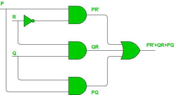
K Map Circuit Diagram
Static Hazards In Digital Logic Geeksforgeeks

Block Diagram Of An Extended K Map Download Scientific Diagram

Digital Circuit And K Map Of A Three Bit Odd Parity Generator
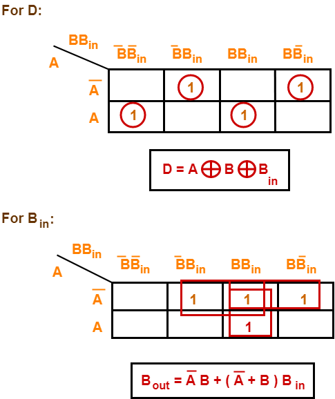
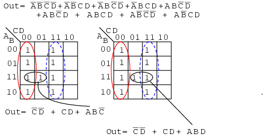
The other truth table outputs b x d from inputs ab01 10 11 are found at corresponding k map locations.

K map circuit diagram. Karnaugh map method or k map method is the pictorial representation of the boolean equations. It explains how to take the data from a truth table and transfer it to a k map. Karnaugh map or k map is introduced by a telecom engineer maurice karnaugh at bell labs in 1953 as a refined technique of edward veitchs veitch diagram and it is a method to simplify or reduce the complexities of a boolean expression. It also handles dont cares.
Cells a and x are adjacent in the k map as ellipses in the left most k map below. Circuit of boolean expression feel free to share this video computer organization and architecture complete video tutorial playlist. See next page for logic diagram circuit analysis simulate circuit for design verification debug fix problems when output is incorrect check truth table against k map population check k map groups against logic equation product terms check logic equations against schematic optimize circuit for area andor performance. Karnaugh map simplifies the boolean algebra expression for the half subtractor circuit.
Gkmap k map disclosure gkmap is a free k map disclosure software which is developed to solve the digital electronics design problems. The karnaugh map km or k map is a method of simplifying boolean algebra expressions. Logic circuit simplification sop and pos this is an online karnaugh map generator that makes a kmap shows you how to group the terms shows the simplified boolean equation and draws the circuit for up to 6 variables. Maurice karnaugh introduced it in 1953 as a refinement of edward veitchs 1952 veitch chart which actually was a rediscovery of allan marquands 1881 logical diagram aka marquand diagram but with a focus now set on its utility for switching circuits veitch charts are therefore also known as marquand.
This is the official method for finding the boolean algebra equation for any circuit. Along with design it also helps in analysis of information flow in the digital circuits. From the above difference and barrow equations we can design the half subtractor circuit diagram using the k map. For three variables 8 combinations the 000 001 011 010 110 111 101 100 sequence is often used.
This video tutorial provides an introduction into karnaugh maps and combinational logic circuits. If a k map is ever needed for a 5 or even more inputs circuit then longer sequences need to be made up that fulfill the rules above.
Full Subtractor Definition Circuit Diagram Truth Table

A Digital Circuit And K Map Of Even Parity Generator B

Use A Karnaugh Map To Find The Equation For A Simpler Circuit With
Https Encrypted Tbn0 Gstatic Com Images Q Tbn 3aand9gctv65fkyjyb2 Sqmpowh Mob6ysjhajx4wu77eec4 Wfs Ipgruauclqbkhimo6umm Usqp Cau
Mealy Model
Lessons In Electric Circuits Volume Iv Digital Chapter 8

Gray Code Binary To Gray Code Converter Electrical4u

Digital Electronics Circuit Optimisation Using K Maps I

The K Map Ppt Download
